Automatic tin soldering equipment for electronic product

A technology for electronic products and automated tin, applied in welding equipment, metal processing equipment, tin feeding devices, etc., can solve the problems of low automation of tin welding equipment, low welding efficiency, cumbersome welding operations, etc., to achieve automatic welding, reduce Labor cost, simple and convenient cleaning effect

Pending Publication Date: 2021-12-10
XIAN TECHNOLOGICAL UNIV
View PDF9 Cites 3 Cited by
  • Summary
  • Abstract
  • Description
  • Claims
  • Application Information

AI Technical Summary

Problems solved by technology

[0004] The existing soldering equipment still has the following technical disadvantages in actual use: the automation of the soldering equipment is low, and the soldering operation is generally performed manually with a hand-held electric soldering iron, and the welding efficiency is low. In addition, the soldering iron often absorbs welding slag when welding, requiring manual Cleaning makes the welding operation more cumbersome, so the present invention proposes an automatic soldering equipment for electronic products

Method used


Image

  • Automatic tin soldering equipment for electronic product
  • Automatic tin soldering equipment for electronic product
  • Automatic tin soldering equipment for electronic product

Examples


Embodiment 1

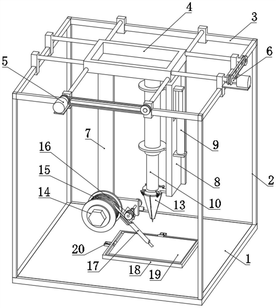
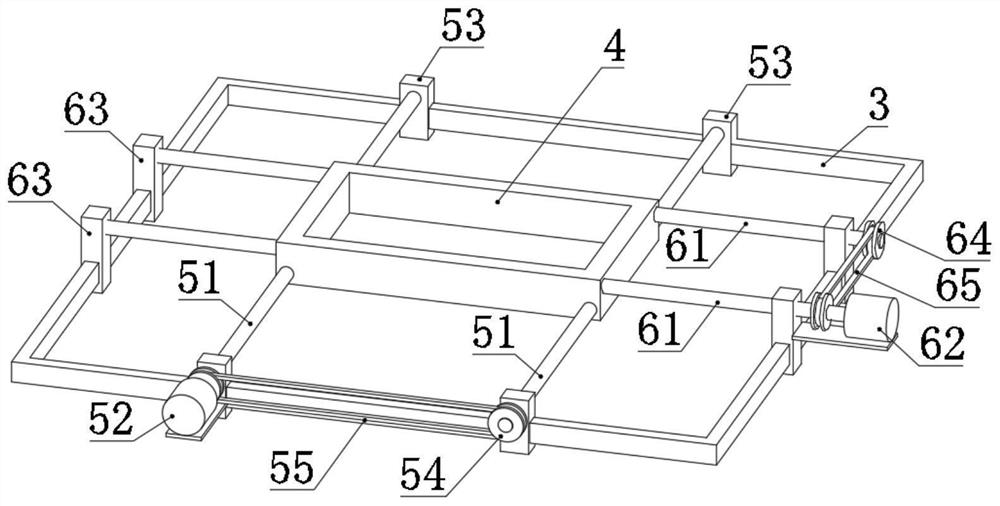
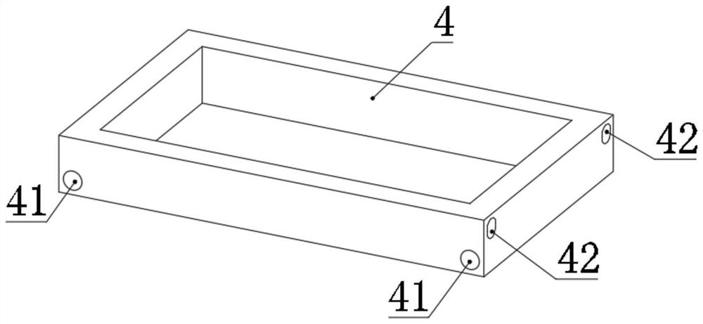
[0052] Refer Figure 1-14 An electronic automatic soldering apparatus, comprising a base plate 1, the upper side of the base plate 1 is attached to the frame 2, the upper frame 2 is attached to the top frame 3, the top side of the movable frame 3 is mounted on the first adjustment means 5 and the second adjusting mechanism 6, the top frame 3 is provided with a central carriage 4, the carriage 4 are mounted a first adjusting mechanism adjusting mechanism 5 and the second 6, the first moving frame 4 through the adjusting mechanism 5 and the second adjustment mechanism 6 drive;

[0053] Lower side of the mobile frame 4 is attached to plate 7 stand, the side stand is attached to the side plate 7 of the frame plate 8, the side of the side frame plate 8 is attached to the cylinder 9, the other end of the side frame plate 8 mounted electric iron 10, electric iron 10 includes a body 101 and a welding cone upper end 102, the body 101 by the telescopic end of the fixed ring 11 and the cylind...

Embodiment 2

[0074] Refer Figure 15-16 On the basis of the above-described embodiment, a negative pressure suction mechanism is mounted between the moving frame 4 and the guide mechanism 17, and the negative pressure gauge mechanism includes a negative pressure fan 21 mounted with the moving frame 4, Also included with the suction tube 22 mounted with the notch guide 171, the suction tube 22 is mounted with the suction port of the negative pressure fan 21.

[0075] The negative pressure fan 21 is tilted along the outer surface of the notch guide 171 by the bracket 23 and the fixed mounting. The bottom end of the suction tube 22 can also be attached to the smoking pipe to improve the effect of smoke absorption.

[0076] When the negative pressure fan 21 operates, the negative pressure is generated to absorb the smoke of the tinning tube 22 to prevent the smoke to affect the health of the person.


PUM


Abstract

The invention discloses automatic tin soldering equipment for an electronic product, and belongs to the field of tin soldering of electronic products. The automatic tin soldering equipment comprises a bottom plate, wherein a frame is installed on the upper side of the bottom plate, a top frame is installed on the upper side of the frame, a first adjusting mechanism and a second adjusting mechanism are movably installed on the upper side of the top frame, a moving frame is arranged in the middle of the top frame, the moving frame is installed with the first adjusting mechanism and the second adjusting mechanism, and the moving frame is driven by the first adjusting mechanism and the second adjusting mechanism. According to the automatic tin soldering equipment, automatic welding of the electronic product can be realized, the operation process is simple, convenient and high in efficiency, welding slag adsorbed on a welding cone of an electric soldering iron can be scraped, normal use of the electric soldering iron is guaranteed, the electronic product can be effectively positioned, random movement during welding is avoided, generated smoke can be adsorbed during welding, and the health of personnel is prevented from being influenced.

Description

Technical field [0001] The present invention relates to the field of electron product soldering technology, in particular to an electronic product automated tin soldering device. Background technique [0002] Soldering is a welding method of penetrating the gap in the gap of the metal member by heating the metal solder by low melting point. Solders are often tin radical alloy, and the soldering iron is heating tool. Widely used in the electronics industry. [0003] According to the search, China Patent No. CN 112722990 A discloses a solder machine device for electronic product processing, including a body: The body is connected by a power cord, which is provided with an axis frame, and an axis frame. The upper rotation is connected to the winding shaft, and the winding shaft is wrapped with tin wire, and the wire wire is provided on the body, and the outlet end of the filament mechanism is provided with a guide hose, and the free end of the guide hose is provided with guidance. H...

Claims


Application Information

Patent Timeline
IPC IPC(8): B23K3/03B23K3/06B23K3/08B23K101/36
CPCB23K3/03B23K3/0607B23K3/087B23K3/08B23K2101/36
Inventor 梁睿
Owner XIAN TECHNOLOGICAL UNIV
Why Eureka
Try Eureka