Underwater transceiving separated water body detection laser radar

A laser detection and separation technology, applied in measuring devices, electromagnetic wave re-radiation, radio wave measurement systems, etc., can solve problems such as scanning difficulties, system power supply difficulties, and azimuth blind spots, so as to reduce system complexity, solar and The sky background noise is small and the effect of improving accuracy

Pending Publication Date: 2021-12-10
XIAMEN UNIV
View PDF7 Cites 0 Cited by
  • Summary
  • Abstract
  • Description
  • Claims
  • Application Information

AI Technical Summary

Problems solved by technology

Therefore, when extracting echo signals and inverting water body parameters, 1) atmospheric correction needs to be performed on the echo signals, and 2) the influence of waves and the interference of the air-sea interface need to be considered, which not only increases the difficulty of signal processing, but also affects the Accuracy of signal extraction and water parameter inversion
3) There is an azimuth blind area, which cannot realize omni-directional scanning in water bodies, nor can it realize layered scanning of water bodies, and the laser detection depth is also limited
[0004] In order to overcome the above difficulties, for shipborne water body lidar, the ideal laser is located directly below the water surface, so as to realize the extraction of optical parameters of the water body that can scan in all directions, but there is a technical bottleneck. 1) If the entire system is placed in the water body 2) After the system is put into the water body, the modules in the system cannot be adjusted; 3) The system contains active devices, and it is difficult to supply power to the system; 4) The system is large in size and heavy in weight. Difficulty scanning in bodies of water

Method used


Image

  • Underwater transceiving separated water body detection laser radar
  • Underwater transceiving separated water body detection laser radar
  • Underwater transceiving separated water body detection laser radar

Examples


Embodiment 1

[0037] The transmitting telescope and the receiving telescope of this embodiment are the transmitting and receiving coaxial telescope 6 , the transmitting and receiving telescopes are shared, and the transmitting and receiving coaxial telescope 6 only includes one.

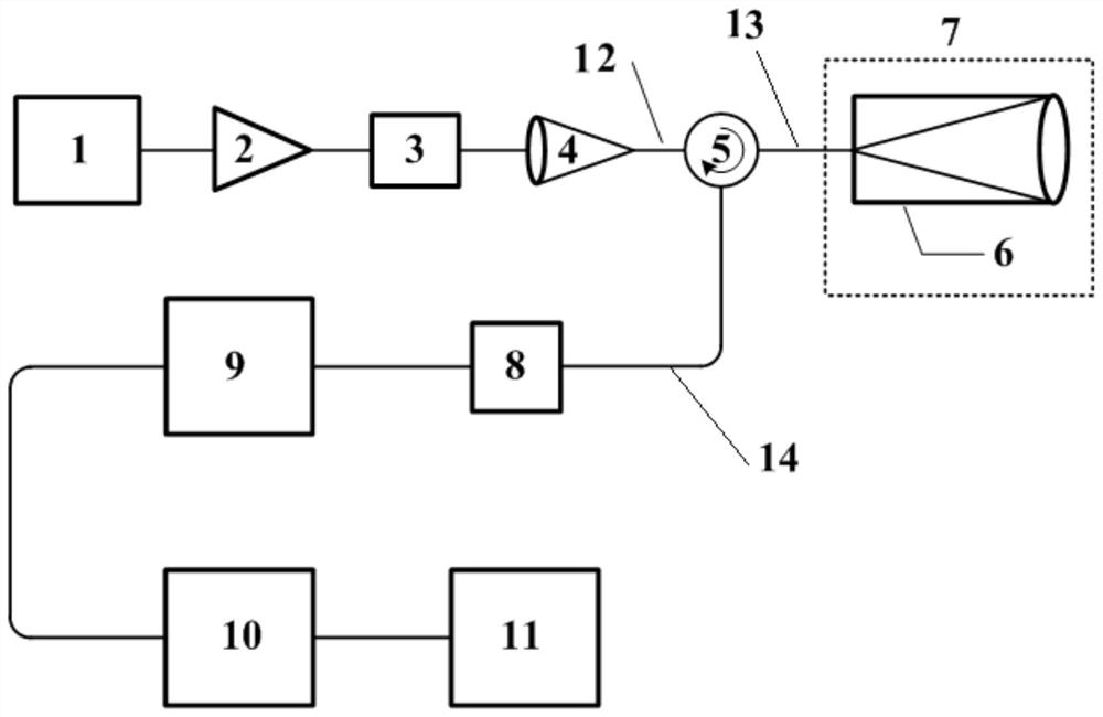
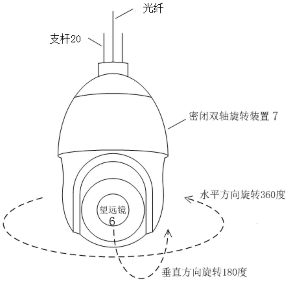
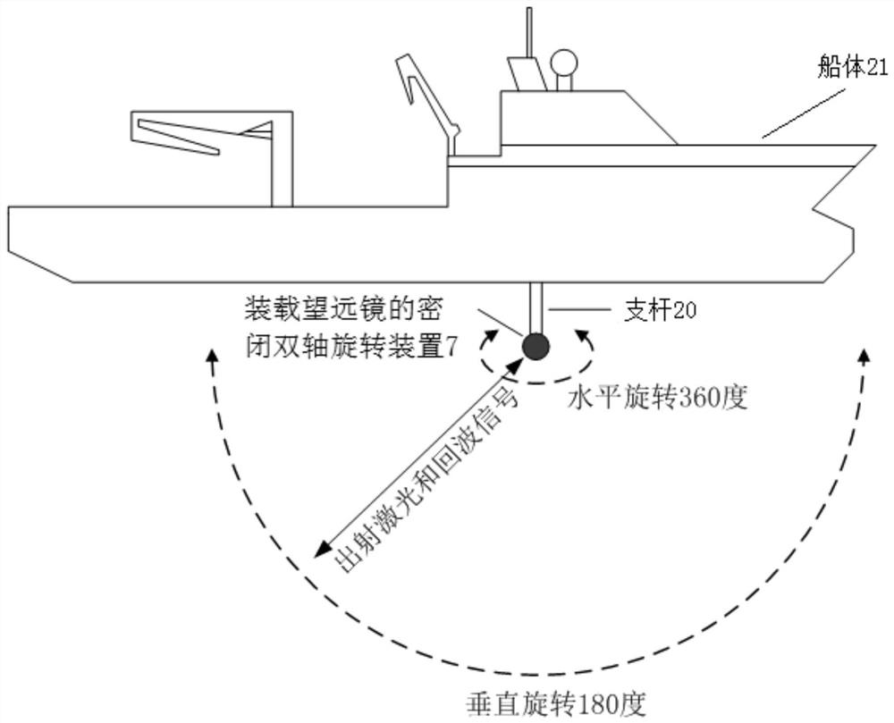
[0038] Specifically, see figure 1As shown, the present embodiment is a separate water detection laser radar for underwater transceiver, including a near-infrared seed laser 1, an amplifier 2, a frequency multiplier 3, a collimator coupler 4, a narrowband filter 8, The detector 9, the acquisition module 10 and the calculation module 11 also include a transceiver coaxial telescope 6 and an airtight two-axis rotary scanning device 7 arranged below the water surface; the transceiver coaxial telescope 6 is arranged on the airtight two-axis rotary scanning device within 7;

[0039] The near-infrared seed laser 1 generates a near-infrared laser in the 1064nm band. After the near-infrared laser is amplified by the amplif...

Embodiment 2

[0060] The difference between this embodiment and the first embodiment lies in the way of generating blue-green band laser light.

[0061] Specifically, see Figure 4 As shown, the present embodiment is a separate water detection lidar for underwater transceiving, including a pulsed blue-green band laser 19, an amplifier 2, a frequency multiplier 3, a collimator coupler 4, and a narrowband filter arranged above the water surface 8. The detector 9, the acquisition module 10 and the calculation module 11 also include a transceiver coaxial telescope 6 and a sealed two-axis rotating scanning device 7 arranged below the water surface; Inside the scanning device 7;

[0062] The pulsed blue-green band laser 19 produces a blue-green band laser, and the blue-green band laser is amplified by the amplifier 2 to generate a 532nm blue-green band laser suitable for water body detection. The laser at this time is spatial light. The space laser is coupled into the optical fiber through the ...

Embodiment 3

[0066] In this embodiment, the transmitting telescope 15 and the receiving telescope 16 are set separately, and each of the transmitting telescope 15 and the receiving telescope 16 includes one.

[0067] Specifically, see Figure 5 As shown, the present embodiment is a separate water detection laser radar for underwater transceiver, including a near-infrared seed laser 1, an amplifier 2, a frequency multiplier 3, a collimator coupler 4, a narrowband filter 8, The detector 9, the collection module 10 and the calculation module 11 also include a transmitting telescope 15, a receiving telescope 16 and an airtight biaxial rotary scanning device 7 arranged under the water surface; In the axial rotation scanning device 7;

[0068] The near-infrared seed laser 1 generates a near-infrared laser in the 1064nm band. After the near-infrared laser is amplified by the amplifier 2, it enters the frequency multiplier 3 to generate a 532nm blue-green band laser suitable for water body detect...


PUM


Abstract

The invention provides an underwater transceiving separated water body detection laser radar which comprises a transmitting telescope and a receiving telescope which are arranged in a closed double-shaft rotary scanning device and placed below the water surface, other components of the separated water body detection laser radar are arranged above the water surface, and the overwater components and the underwater components are connected on an optical path through optical fiber cables. Laser emission and echo receiving are both carried out in the water body, so that echo information does not need to be subjected to atmospheric correction, the influence of waves and the interference of an air-sea interface do not need to be considered, the background noise of the sun and the sky is small, the signal processing difficulty can be reduced, and the precision of echo signal extraction and water body parameter inversion can be improved. Besides, the transceiving telescope arrays are placed at different water depths, evolution conditions of properties and sizes of particles in the ocean in the descending process can be detected, quantitative description of the ocean carbon sink process is achieved, and meanwhile layered information detection of biological populations in the ocean can also be achieved.

Description

technical field [0001] The invention relates to the technical field of laser radar, in particular to a separated underwater detection laser radar for transmitting and receiving underwater. Background technique [0002] Lidar can penetrate water bodies to obtain accurate information on the upper surface of water bodies. The existing water body detection lidar is based on ship-borne, airborne or space-borne platforms, which can detect a wide range of ocean water body information. [0003] However, since the laser emitting and echo receiving telescopes are located above the water surface at this time, the laser needs to pass through the atmosphere and the air-sea interface and finally enter the water body after being emitted from the telescope, and the echo signal also needs to pass through the air-sea interface and the atmosphere to be finally received by the telescope. . Therefore, when extracting echo signals and inverting water body parameters, 1) atmospheric correction n...

Claims


Application Information

Patent Timeline
Patent Type & Authority Applications(China)
IPC IPC(8): G01S7/481G01S17/02
CPCG01S7/4811G01S17/02
Inventor 上官明佳杨志峰李忠平商少凌
Owner XIAMEN UNIV
Why Eureka
Try Eureka