Magnetic robot driving device

A driving device and robot technology, applied in electromechanical devices, electric components, electrical components, etc., can solve the problems of large friction between the permanent magnet and the partition part, large heat generation, small working space, etc., to achieve large-scale adjustment, reduce Coupling effect, pure effect of output magnetic field

Pending Publication Date: 2021-12-14
SUZHOU UNIV
View PDF0 Cites 0 Cited by
  • Summary
  • Abstract
  • Description
  • Claims
  • Application Information

AI Technical Summary

Problems solved by technology

[0006] 1. The driving device of a micro-scale magnetic robot based on a permanent magnet array is generally realized by using a stepping motor to rotate a permanent magnet or a permanent magnet array. This type of magnetic field can generate a large magnetic field or a magnetic gradient field (>100mT); but , the driving device of a micro-scale magnetic robot based on a permanent magnet depends on the physical connection between the permanent magnet and the actuator, the direction of the magnetic field cannot be changed flexibly, and is limited by the inherent properties of the mechanical equipment. This type of device is difficult to achieve rapid changes in the surrounding magnetic field. The provided rotating magnetic field is often below 50 Hz, making it difficult to achieve high-speed movement of micro-scale magnetic robots;
[0007] 2. The Helmholtz coil is assembled into a multi-layer nested electromagnetic coil, which realizes a small-scale uniform magnetic field inside, and realizes the generation of a controllable magnetic field by changing the voltage signal at both ends of the coil winding; however, the existing The driving device of the electromagnetic coil has the problems of weak magnetic field (generally a few millites to a dozen millites), small working space, and large heat generation, which is difficult to meet the efficient control of the robot's motion behavior with weak magnetism;
[0008] 3. The composite drive device consists of two parts, the electromagnetic module and the permanent magnet module. Since the electromagnetic coil generates a magnetic field when it is energized, the permanent magnet and the coil attract or repel each other, resulting in the instability of the permanent magnet.
However, ① the current permanent magnets in this type of device are in direct contact with the partition part, so that the contact friction between the two affects the movement behavior of the magnetic ball
②Because the magnetic field strength decreases extremely rapidly with distance (proportional to the reciprocal of the square of the distance), the range of action of the magnetic field in this type of device is limited, and it is difficult to achieve large-distance control of micro-scale magnetic robots
③In addition, this type of system uses an electromagnetic coil with a magnetic core. Although the effect of the electromagnetic force is enhanced, the magnetic core will also be magnetized by the permanent magnet when it is magnetized by the coil, generating a parasitic magnetic field. Magnetic field coupling is difficult to generate a pure magnetic field. On the other hand, there is a gradient force pointing to the coil between the coil core and the permanent magnet. On the one hand, the friction between the permanent magnet and the partition part is very large;
Some existing technologies have a series of technical defects, making it difficult to achieve high-speed operation and large-scale motion control of micro-scale magnetic robots, which greatly limits the development of such robots in the fields of biomedicine, micro-manipulation, and intelligent manufacturing.

Method used


Image

  • Magnetic robot driving device
  • Magnetic robot driving device
  • Magnetic robot driving device

Examples


Embodiment 1

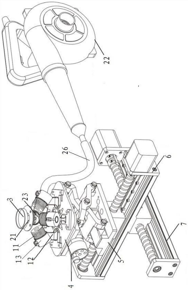
[0041] see figure 1 and figure 2 , as shown in the legend therein, a magnetic robot driving device includes a driving device body unit, and the above-mentioned driving device body unit includes:

[0042] A plurality of electromagnetic modules 1, each of the above-mentioned electromagnetic modules 1 includes an electromagnetic coil 11 that generates a magnetic field after being energized and a first bracket assembly for supporting the above-mentioned electromagnetic coil, and a plurality of the above-mentioned electromagnetic modules generate a composite magnetic field;

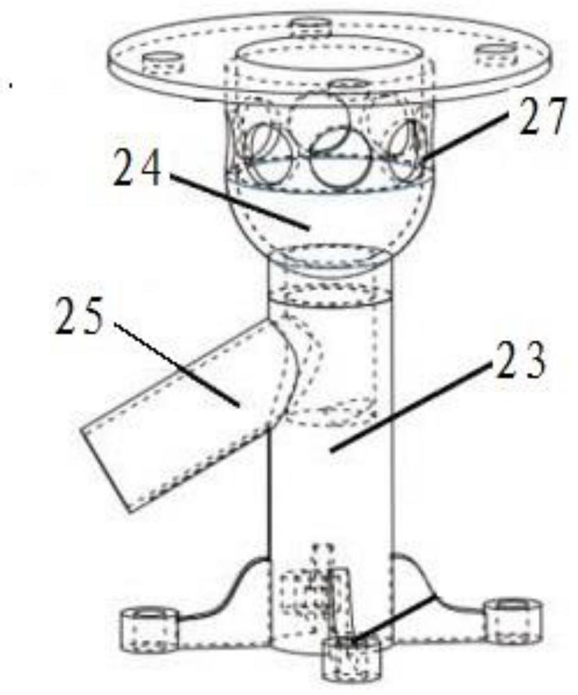
[0043] A permanent magnet module 2, the permanent magnet module 2 includes a spherical permanent magnet 21 that generates a driving magnetic field after moving under the action of the above-mentioned composite magnetic field, a blower 22 for providing airflow, and is used to support the spherical permanent magnet 21 and guide the airflow to the above-mentioned Below the spherical permanent magnet 21 is a sec...


PUM


Abstract

The invention discloses a magnetic robot driving device which comprises a driving device body unit, the driving device body unit comprises a plurality of electromagnetic modules and a permanent magnet module, each electromagnetic module comprises an electromagnetic coil generating a magnetic field after being electrified and a first support assembly used for supporting the electromagnetic coil, and the plurality of electromagnetic modules generate a composite magnetic field. The permanent magnet module comprises a spherical permanent magnet which generates a driving magnetic field after moving under the action of the composite magnetic field, an air blower used for providing airflow and a second support assembly used for supporting the spherical permanent magnet and guiding the airflow to the position below the spherical permanent magnet so as to drive the spherical permanent magnet to suspend. According to the invention, constraint of the position of the permanent magnet and isolation of the permanent magnet from the electromagnetic coil are achieved in an air suspension mode, the friction force borne by the permanent magnet during movement is greatly reduced, so that the device has higher responsiveness and higher speed, and the problem that an existing micro-scale robot is low in rotating speed under the low Reynolds number is solved.

Description

technical field [0001] The invention belongs to the technical field of robot drive control, in particular to the technical field of microscale magnetic robot drive devices. Background technique [0002] The information disclosed in this Background section is only intended to enhance the understanding of the general background of the present invention, and should not be considered as an acknowledgment or any form of suggestion that the information constitutes the prior art that is already known to those skilled in the art. [0003] The motion control of micro-scale magnetic robots can be realized by using magnetic fields. At present, the driving device that can control the motion behavior of micro-scale magnetic robots by generating a specific magnetic field is generally composed of permanent magnets, electromagnetic coils (such as Helmholtz coils) or a combination of both. composition. The micro-scale magnetic robot drive device based on permanent magnets often generates a ...

Claims


Application Information

Patent Timeline
Patent Type & Authority Applications(China)
IPC IPC(8): H02K33/18H02K41/06
CPCH02K33/18H02K41/06
Inventor 范新建杨湛蒋奕晖孙立宁
Owner SUZHOU UNIV
Why Eureka
Try Eureka