
Surface cleaning equipment and self-cleaning mopping control method thereof

A surface cleaning and control method technology, which is applied in cleaning equipment, cleaning action control, and automatic control of traveling motion, etc., can solve the problems of high power consumption and water consumption, difficult self-cleaning of rags, and poor battery life, so as to reduce work power consumption water consumption, improve cleaning efficiency, and reduce power consumption

Pending Publication Date: 2021-12-17
NINGBO SAWADIKA ELECTRICAL APPLIANCE
View PDF7 Cites 1 Cited by
  • Summary
  • Abstract
  • Description
  • Claims
  • Application Information

AI Technical Summary

Problems solved by technology

[0002] Surface cleaning equipment is a common household cleaning equipment, including sweeping robots, washing machines, etc., which are often used for cleaning and mopping the floor; existing sweeping robots usually hang a rag on the bottom and drop the water from the water tank on the rag , the sweeping robot wipes the ground with a rag during the movement process. However, the rag of this type of sweeping robot is difficult to self-clean during the travel process. It needs to be disassembled and cleaned or cleaned in the cleaning base station, which is troublesome and time-consuming; now In the process of moving and mopping the floor of some drum-type floor washing machines, the drum rotates 360° and sprays clean water to the drum through the water spraying system for wetting and cleaning. Such equipment consumes a lot of power and water and has poor battery life.

Method used


Image

  • Surface cleaning equipment and self-cleaning mopping control method thereof
  • Surface cleaning equipment and self-cleaning mopping control method thereof
  • Surface cleaning equipment and self-cleaning mopping control method thereof

Examples


Embodiment Construction

[0027] A specific embodiment of the present invention will be described in detail below with reference to the accompanying drawings, but it should be understood that the protection scope of the present invention is not limited by the specific embodiment.

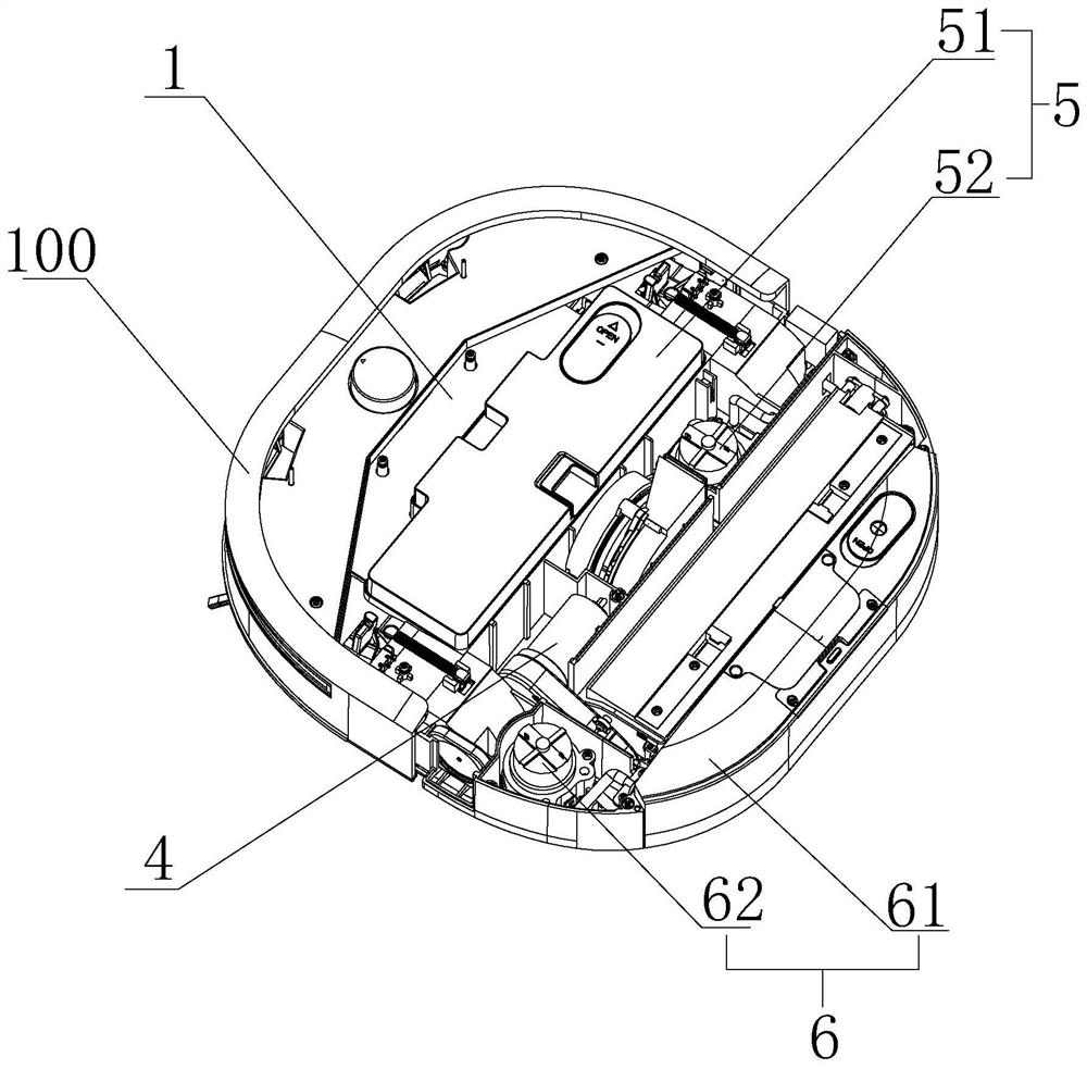
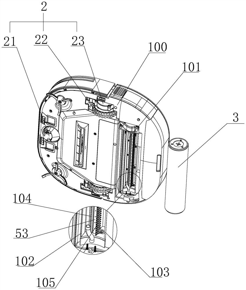
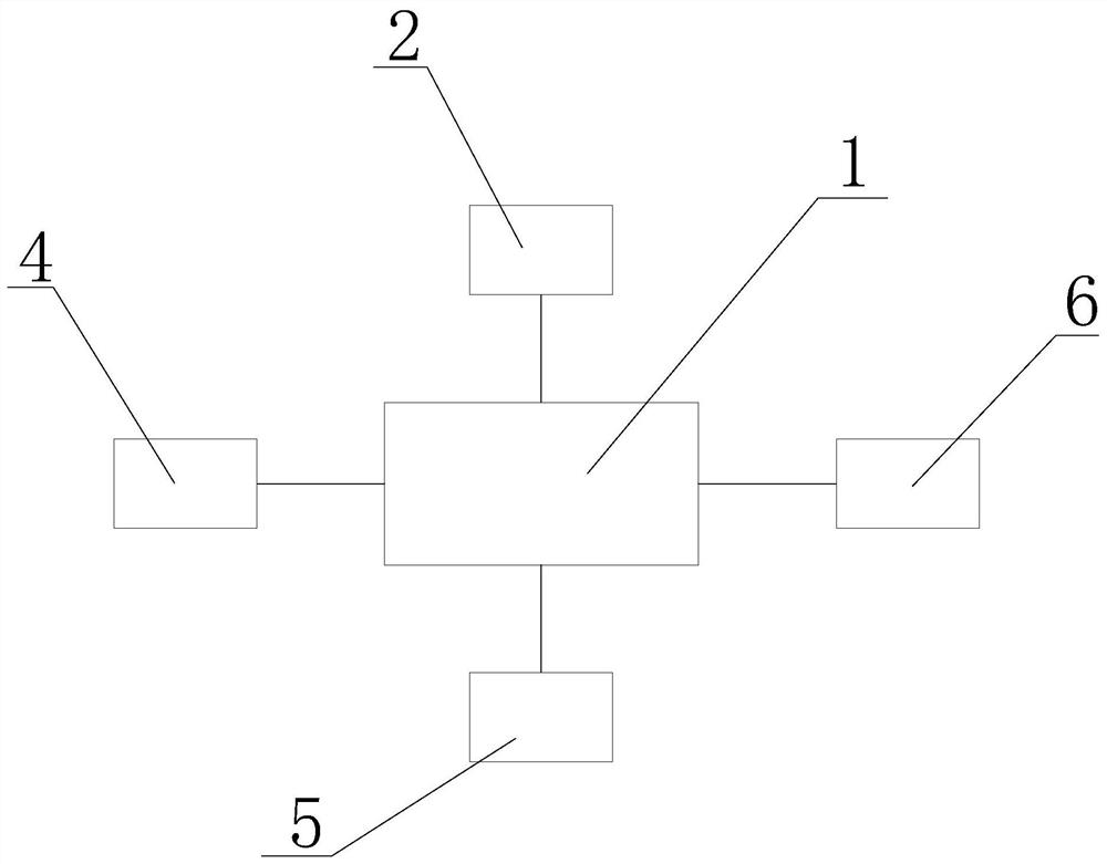
[0028] A surface cleaning device of the present invention such as figure 1 As shown, it includes a main engine 100, which is provided with a control system 1, a drive wheel 22 assembly 2, a drum assembly 3, a drum driving mechanism 4, a clean water spray system 5 and a sewage recovery system 6; the main engine 100 is formed corresponding to its rear end. There is an accommodating cavity 101 with an opening facing downward, and the drum assembly 3 is detachably installed in the accommodating cavity 101. A cleaning cavity is formed between the upper part of the accommodating cavity 101 and the drum assembly 3, and the drum driving mechanism 4 is used for Receive the command from the control system 1 to drive the drum assembly ...


PUM


Abstract

The invention discloses surface cleaning equipment and a self-cleaning mopping control method thereof. The surface cleaning equipment comprises a main machine, a control system, a driving wheel assembly, a roller assembly, a roller driving mechanism, a clean water spraying system and a sewage recycling system. A containing cavity with a downward opening is formed in the main machine, the roller assembly is installed in the containing cavity, a cleaning cavity is formed between the upper portion of the containing cavity and the roller assembly in a matched mode, and the roller driving mechanism is used for driving the roller assembly to rotate. The driving wheel assembly is installed at the front end of the bottom of the host and used for receiving instructions of the control system to drive the host to move. The clear water spraying system is used for spraying clear water to the roller and the sewage recycling system is used for recycling sewage formed in the cleaning cavity. According to the invention, the ground is wiped through the roller, self-cleaning of the roller can be achieved in the wiping process, and the cleaning effect of the device is greatly improved; and meanwhile, the control method of the equipment can greatly reduce the working power consumption and water consumption, and the cruising ability is effectively improved.

Description

technical field [0001] The invention relates to the technical field of cleaning equipment, in particular to a surface cleaning equipment and a self-cleaning mopping control method thereof. Background technique [0002] Surface cleaning equipment is a common household cleaning equipment, including sweeping robots, washing machines, etc., which are often used for cleaning and mopping the ground; most existing sweeping robots use a rag on the bottom and drop the water from the water tank on the rag. , the sweeping robot wipes the ground with a rag during the movement process. However, the rag of this type of sweeping robot is difficult to self-clean during the traveling process. It needs to be disassembled for cleaning or cleaned in the cleaning base station, which is troublesome and time-consuming; In the process of moving and mopping the floor of some drum-type washing machines, the drum rotates 360° and sprays clean water to the drum through the clean water spray system for ...

Claims


Application Information

Patent Timeline
IPC IPC(8): A47L11/30A47L11/40
CPCA47L11/30A47L11/40A47L11/4011A47L11/4041A47L11/4063A47L11/4088A47L11/4016A47L11/4072A47L2201/04A47L2201/06
Inventor 俞少蔚
Owner NINGBO SAWADIKA ELECTRICAL APPLIANCE
Learn More