Eureka AIR delivers breakthrough ideas for toughest innovation challenges, trusted by R&D personnel around the world.

Novel environment-friendly electrostatic dust collector and application thereof

A technology of electrostatic precipitator and precipitator, which is applied in the field of dual power supply power supply discharge and dust collection integrated plate, brush roller dust removal electrostatic precipitator, can solve the problem that the dust collection cannot be improved, and achieve the reduction of secondary dust, Easy maintenance and thorough ash removal

Active Publication Date: 2021-12-17
QINHUANGDAO SANGGE ELECTRICAL CONTROL EQUIP CO LTD
View PDF18 Cites 1 Cited by
  • Summary
  • Abstract
  • Description
  • Claims
  • Application Information

AI Technical Summary

Problems solved by technology

[0005] However, the above-mentioned prior art cannot achieve the purpose of improving dust collection capacity and efficient dust collection.

Method used


Image

  • Novel environment-friendly electrostatic dust collector and application thereof
  • Novel environment-friendly electrostatic dust collector and application thereof
  • Novel environment-friendly electrostatic dust collector and application thereof

Examples


example 1

[0056] Experiment A: First, the existing structure of the dust collector is used for the test. The volume width is 3m, the length is 10m, and the height is 6m. The electric field of the dust collector is formed by the cathode of the discharge prickly wire and the anode of the dust collection plate, and the distance between the different poles is 220mm. ;The power supply adopts a single-phase negative output high-frequency soft and stable power supply. The wiring method is: the high-voltage output end of the power supply is connected to the discharge electrode needle-type cathode line; the other end of the power supply is connected to the dust collection plate, and the dust collection plate is grounded together with the dust collector shell. . The data after electrification is: voltage 83kv, current 60mA. The flue gas volume is 30,000 m3 / h, and the inlet concentration is 3g / m3. After treatment, the emission concentration is 57mg / m3.

[0057] Experiment B: Under the condition ...

example 2

[0068] Experiment A: First, the existing dust collector structure is used for the test. The volume width is 3m, the length is 10m, and the height is 6m. The electric field of the dust collector is formed by the cathode of the discharge prickly wire and the anode of the dust collection plate, and the distance between the different poles is 400mm. ;The power supply adopts a single-phase negative output high-frequency soft and stable power supply, and the wiring method is: the high-voltage output end of the power supply is connected to the needle-type cathode line of the discharge electrode; . The data after electrification is: voltage 130kv, current 80mA. The flue gas volume is 30,000 m3 / h, and the inlet concentration is 3g / m3. After treatment, the emission concentration is 50mg / m3.

[0069] Experiment B: Under the condition that the volume width of the precipitator is 3m, the length is 10m, and the height is 6m, the new environmental protection electrostatic precipitator tech...


PUM


Abstract

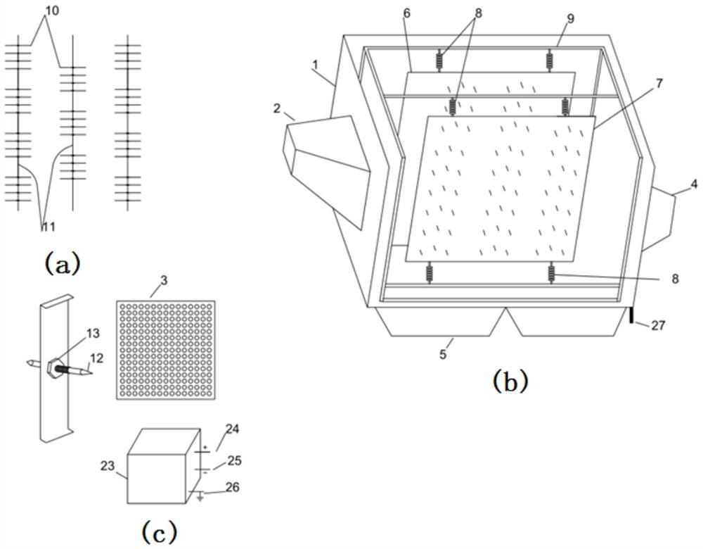
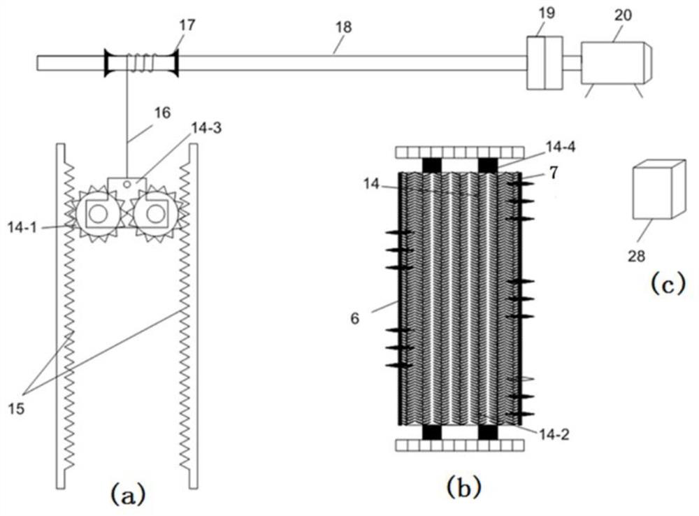
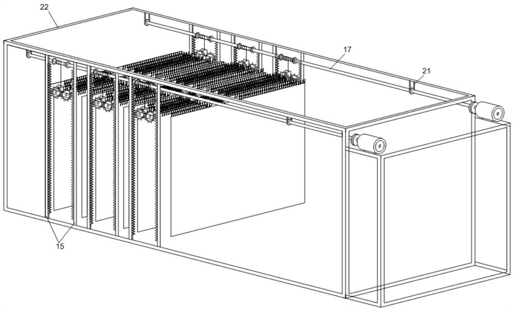
The invention discloses a novel environment-friendly electrostatic dust collector and application thereof. A pole plate mounting hanging beam is mounted on a main frame in the dust collector. A positive discharge and dust collection integrated pole plate and a negative discharge and dust collection integrated pole plate are mounted on the pole plate mounting hanging beam by hoisted positive and negative discharge and dust collection integrated pole plate insulators. The power supply positive high-voltage output of a dual-output high-frequency soft stable power supply is connected with the positive discharge and dust collection integrated pole plate, the power supply negative high-voltage output end of the dual-output high-frequency soft stable power supply is connected with the negative discharge and dust collection integrated pole plate, and the power grounding end is connected with the grounding end of a dust collector shell. The dust of the positive and negative discharge and dust collection integrated pole plates is removed by a brush roller in an up-and-down rotating mode.

Description

technical field [0001] The invention belongs to the technical field of dust collectors, and relates to a novel environment-friendly electrostatic precipitator and its application, and more specifically relates to an electrostatic precipitator with dual power supply, discharge and dust collection integrated pole plate, and brush roller dust removal. Background technique [0002] Electrostatic precipitator is a kind of flue gas dust removal method. The electric field of the dust collector is mainly formed by the cathode of the discharge burr wire and the anode of the dust collecting plate. When the dusty flue gas passes by, the dust particles and negative ions are combined with negative charges, and tend to the surface of the anode to deposit. At present, the common electrostatic precipitator basically adopts the method of hanging the cathode line to discharge and the anode plate to collect dust; while the dust on the anode plate and cathode line is rapped or sound vibration m...

Claims


Application Information

Patent Timeline
Patent Type & Authority Applications(China)
IPC IPC(8): B03C3/34B03C3/41B03C3/47B03C3/74
CPCB03C3/34B03C3/41B03C3/47B03C3/743
Inventor 李珣李春祥张凡振
Owner QINHUANGDAO SANGGE ELECTRICAL CONTROL EQUIP CO LTD
Why Eureka
Eureka Blog
Learn More