
Oil pump shell machining method

A technology of an oil pump housing and a processing method, which is applied in the field of cutting processing technology, can solve problems such as affecting the processing accuracy and processing quality of parts, greatly affecting the processing accuracy and processing quality, and irregular shape of workpieces, so as to improve production or manufacturing efficiency. , The effect of stable and reliable clamping and reduced processing cost

Active Publication Date: 2021-12-17
贵州凯星液力传动机械有限公司
View PDF6 Cites 1 Cited by
  • Summary
  • Abstract
  • Description
  • Claims
  • Application Information

AI Technical Summary

Problems solved by technology

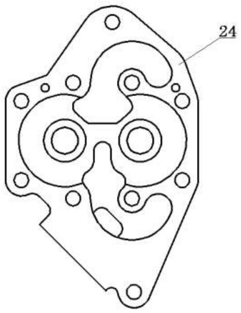
The existing oil pump casing processing process is: casting forming, annealing, sandblasting, milling rough machining, scribing position line and inclined plane position line, drilling or reaming hole features, milling finishing, grinding, drilling, Deburring: In the existing oil pump casing processing process, due to the extremely irregular shape of the workpiece, it is impossible to perform effective clamping and select a suitable positioning datum surface especially in the milling rough machining process, which not only makes the workpiece The process cannot be aligned, which affects the processing accuracy, and also has a great impact on the processing accuracy and processing quality of several subsequent processes, affecting the overall processing accuracy and processing quality of the parts, and because the outer surface of the oil pump housing needs to be cut and formed There are many characteristic elements and the processing efficiency is low. Therefore, it is urgent to improve the design of its processing technology.

Method used


Image

  • Oil pump shell machining method
  • Oil pump shell machining method
  • Oil pump shell machining method

Examples


Embodiment Construction

[0030] The technical solution of the present invention is further described below, but the scope of protection is not limited to the description.

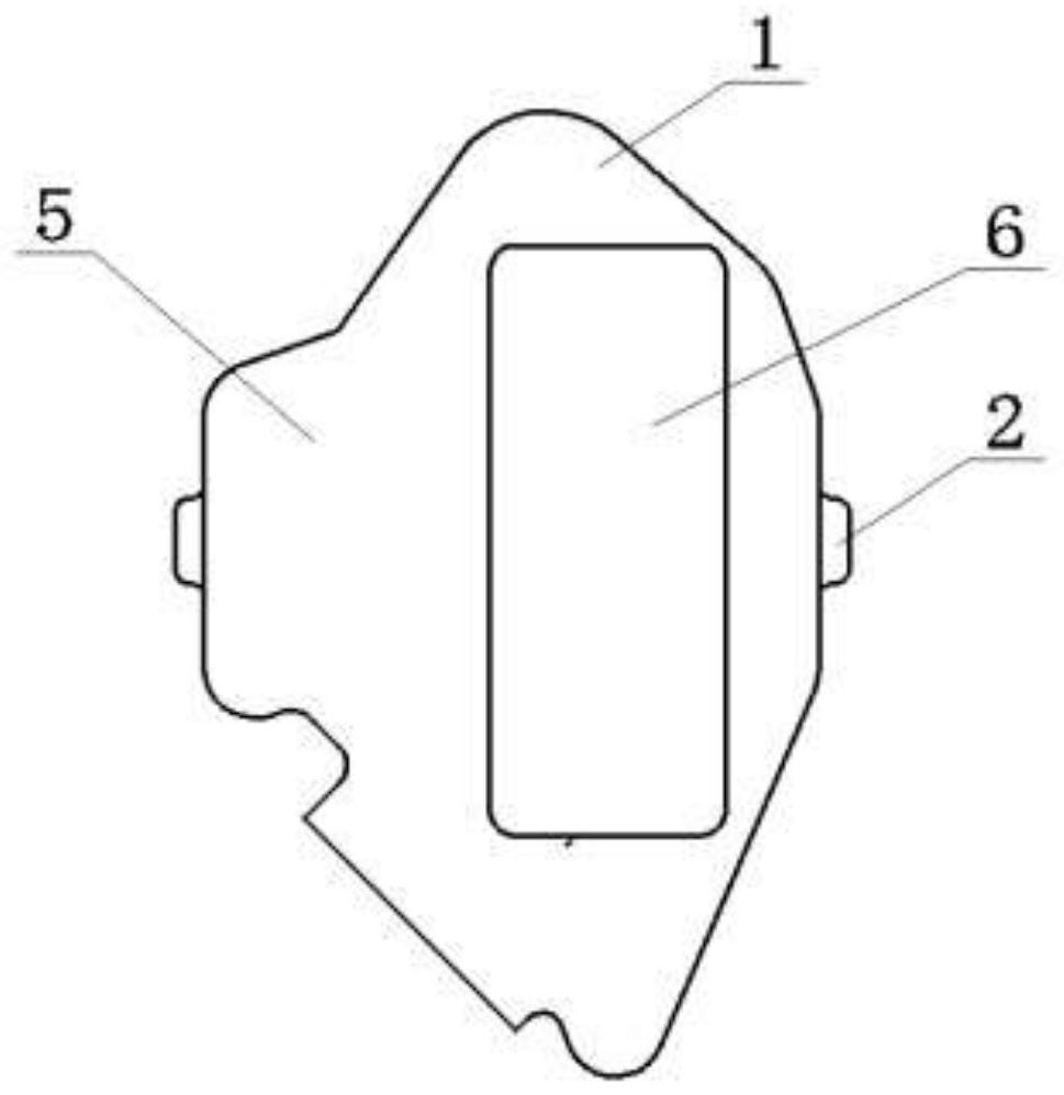
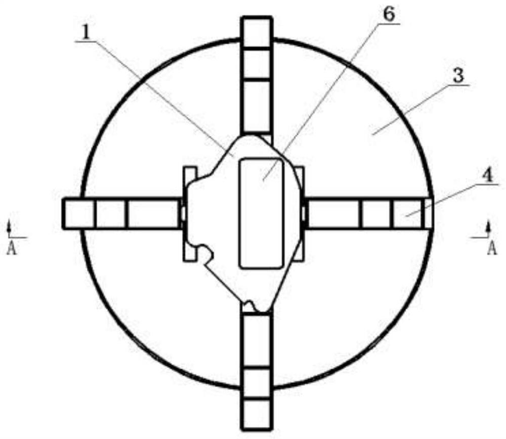
[0031] Such as Figure 1 to Figure 8 As shown, the present invention provides a method for processing an oil pump casing, comprising the following steps:

[0032] Step 1: According to the shape of the pattern in the pre-drawn design drawings, the blank 1 is produced by casting technology, and at least a pair of process convex towers 2 are evenly arranged around the blank 1;

[0033] Step 2: Provide machine tools;

[0034] Step 3: Provide a chuck 3, install the chuck 3 on the machine tool table, at least two pairs of claws 4 are installed on the chuck 3, and clamp at least one pair of process convex towers 2 between the pair of claws 4 The blank 1 in the step 1 is clamped on the chuck 3, the outer surface of the blank 1 is milled by the machine tool to obtain the datum plane 5, and then a datum hole 6 is milled in the datum plane ...


PUM


Abstract

The invention provides an oil pump shell machining method. The oil pump shell machining method comprises the following steps that a blank is prepared through a casting method, and at least one pair of technological convex towers are arranged on the periphery of the blank; a machine tool is provided; a chuck is provided and installed on a machine tool workbench, the blank is clamped through the chuck, and the datum plane and the datum hole are milled; a drilling and milling clamp is provided, the blank is clamped through the drilling and milling clamp, and all shape element characteristics are cut and machined; and a supporting clamp is provided, the blank is clamped through the supporting clamp, and milling is performed to remove the technological convex towers. With adoption of the technical scheme, through the procedures of sequentially arranging the technological convex towers, machining the datum plane and the datum hole and the like, the workpiece can be conveniently and stably clamped through a jaw on the chuck in the rough milling procedure, stable clamping and workpiece alignment are facilitated through the datum hole and the datum plane in the other procedures, the overall machining precision and machining quality of the workpiece are improved, the auxiliary process time is shortened, and the production efficiency is improved.

Description

technical field [0001] The invention relates to the technical field of cutting processing technology, in particular to a processing method for an oil pump casing. Background technique [0002] At present, cutting processing is still the main processing method for producing or manufacturing mechanical parts. In the cutting process, in order to ensure the processing accuracy of parts, it is necessary to select the corresponding surface on the workpiece surface as a positioning reference before processing. For workpieces with regular shapes, the positioning datum is easy to select. However, for parts with complex shapes and many shape feature elements that need to be machined, it is difficult to select a reasonable positioning datum. For example, the oil pump casing is the appearance structure of the oil pump. The blank is made of ductile iron with irregular shape, so it is not easy to clamp during processing. The processing surface includes flat surface, inclined surface, int...

Claims


Application Information

Patent Timeline
Patent Type & Authority Applications(China)
IPC IPC(8): B23P15/00F04D29/40
CPCB23P15/00F04D29/40
Inventor 叶义书
Owner 贵州凯星液力传动机械有限公司
Learn More