Metal electrolysis equipment and anode structure

A metal electrolysis and anode structure technology, applied in the direction of electrodes, electrolysis process, electrolysis components, etc., can solve the problems of unstable current, affecting the efficiency of electrolysis, and easy to generate fluctuations, so as to improve the service life, ensure the efficiency of electrolysis, and prevent oxidation and corrosion Effect

Pending Publication Date: 2021-12-17
TIANQI LITHIUM CORP
View PDF2 Cites 0 Cited by
  • Summary
  • Abstract
  • Description
  • Claims
  • Application Information

AI Technical Summary

Problems solved by technology

For example 1. The anode is connected to the electrode through connectors (such as bolts, mortise joints and locks, etc.), the contact area of ​​the connection position is small, the current is unstable during electrolysis, and it is easy to fluctuate, which affects the efficiency of electrolysis
2. The contact area of ​​the connection position is small, the resistance is large, and the connection part is prone to heat, resulting in deformation of the connection parts and affecting the service life
3. Both graphite anodes will have a section of graphite involved in the assembly and fixing, not opposite to the cathode plate, only providing current but not participating in electrolysis, resulting in waste of anode graphite
4. The upper end of the plug-in anode graphite is in contact with air, and it is easily oxidized and corroded at high temperature, which affects the service life
5. The lower plug-in graphite anode has strict assembly process requirements, high installation cost, inconvenient graphite replacement, and high scrap rate of the tank body
The above two patents can improve the shortcomings of the electrolytic cell to a certain extent by changing the anode connection method, but they are not effective solutions

Method used


Image

  • Metal electrolysis equipment and anode structure
  • Metal electrolysis equipment and anode structure
  • Metal electrolysis equipment and anode structure

Examples


Embodiment Construction

[0025] The present invention will be further described below in conjunction with the accompanying drawings and embodiments.

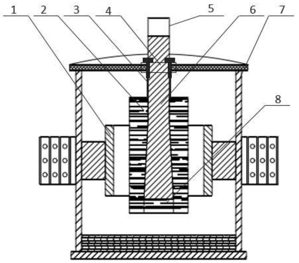
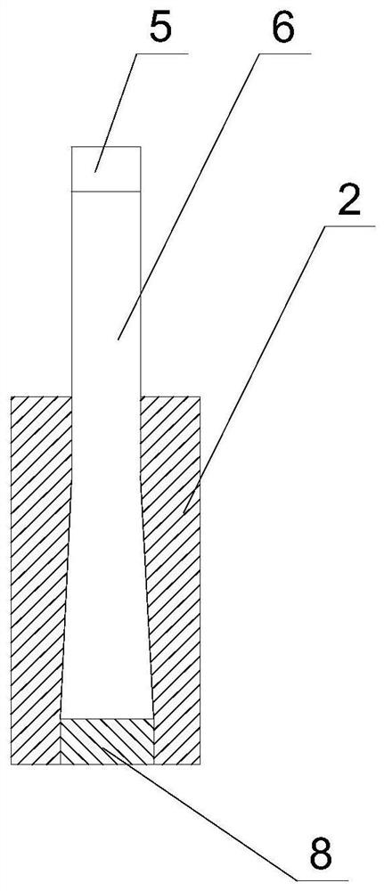
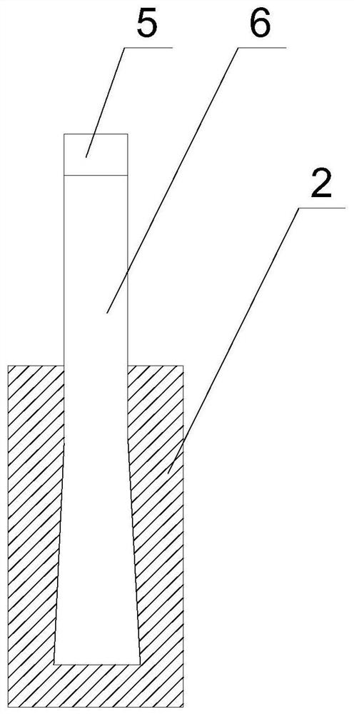
[0026] Such as figure 1 As shown, the metal electrolysis equipment of the present invention includes an electrolytic cell 7 and an anode structure, the electrolytic cell 7 is provided with a cathode 1, the anode structure includes an anode 2 and an anode tab 6, and the anode 2 is located in the electrolytic cell 7 It is inside and sleeved on the outer wall of the anode tab 6 , and one end of the anode tab 6 passes through the electrolytic cell 7 and is located outside the electrolytic cell 7 .

[0027] Electrolyzer 7 comprises tank body and tank cover, is existing conventional structure. The cathode 1 is used to cooperate with the anode 2 to complete the electrolysis reaction. The anode 2 is made of graphite anode. By placing the anode 2 completely inside the electrolytic cell 7 and not in contact with the outside air, it can effectively prevent the a...


PUM


Abstract

The invention provides metal electrolysis equipment and an anode structure. The metal electrolysis equipment comprises an electrolytic tank and the anode structure, wherein a cathode is arranged in the electrolytic tank; the anode structure comprises an anode and an anode tab; the anode is located in the electrolytic tank and sleeves the outer wall of the anode tab; and one end of the anode tab penetrates through the electrolytic tank and is located outside the electrolytic tank. Due to the fact that the anode sleeves the outer wall of the anode tab, the contact area between the anode and the anode tab is large, the current is stable during electrolysis, fluctuation cannot be generated, electrolysis efficiency is guaranteed, resistance is reduced, the connecting position of the anode and the anode tab is not prone to heating, the problem that a connecting piece deforms does not exist, and therefore the service life of the anode structure is prolonged; and due to the fact that the whole anode is located in the electrolytic tank, all anode materials can participate in electrolysis, the situation of anode waste does not exist, and the service life is longer.

Description

technical field [0001] The invention relates to the field of electrolytic equipment, in particular to a metal electrolytic equipment and an anode structure. Background technique [0002] At present, the common method of electrolytic preparation of metals in the industry is molten salt electrolysis, such as the electrolytic preparation of metal magnesium, sodium, calcium and lithium, etc., which are prepared by electrolyzing chloride mixed molten salts at high temperature to prepare various metals. Therefore, in the electrolysis process, the most critical equipment is the electrolysis cell, and the installation, operating parameters and service life of the electrolysis cell are closely related to the cost of electrolysis. An electrolyzer is usually composed of an inner and outer tank body, a tank cover, a cathode, an anode, a power supply and a gas absorption device, etc., and its components will have an impact on the operation and service life of the electrolyzer, especially...

Claims


Application Information

Patent Timeline
Patent Type & Authority Applications(China)
IPC IPC(8): C25C7/00C25C7/02
CPCC25C7/005C25C7/025
Inventor 王苏刘强邹崴周复
Owner TIANQI LITHIUM CORP
Why Eureka
Try Eureka