Methods of using microfluidic positional encoding devices

A microfluidic, device technology that uses microfluidic position-encoded devices to address issues that slow down the development of new diagnostic and therapeutic methods

Pending Publication Date: 2021-12-17
艾勒根公司
View PDF58 Cites 0 Cited by
  • Summary
  • Abstract
  • Description
  • Claims
  • Application Information

AI Technical Summary

Problems solved by technology

However, ordering large quantities of DNA fragments from existing DNA suppliers can result in waiting days or even weeks
This delay incurs significant hidden financial and opportunity costs and essentially slows the pace of development of new diagnostics and treatments

Method used


Image

  • Methods of using microfluidic positional encoding devices
  • Methods of using microfluidic positional encoding devices
  • Methods of using microfluidic positional encoding devices

Examples


preparation example Construction

[0412] In various embodiments, peptide synthesis is performed in or on a unit of the microfluidic device described herein. In some cases, peptide synthesis is accomplished using solid-phase peptide synthesis. Peptide synthesis methods used in accordance with various embodiments may include microwave-assisted peptide synthesis and methods of peptide synthesis utilizing photolabile linkers and UV radiation (see, eg, Qvortrup et al., Organic Letters 2014, 16:4782-85. Either or A plurality of reagents for peptide synthesis can be delivered to the units described herein in the microfluidic devices described herein. The reagents for peptide synthesis can comprise one or more of the following: Carbodiimides such as dicyclohexyl Carbodiimide (DCC), Diisopropylcarbodiimide (DIC); Triazoles such as 1-hydroxybenzotriazole (HOBt), 1-hydroxy-7-aza-benzotriazole (HOAt) ); ethyl cyanohydroxyiminoacetate (oxyma); hexafluorophosphate azabenzotriazole tetramethyl uranium (HATU); hexafluorophos...

Embodiment 1

[0524] Position coding device architecture

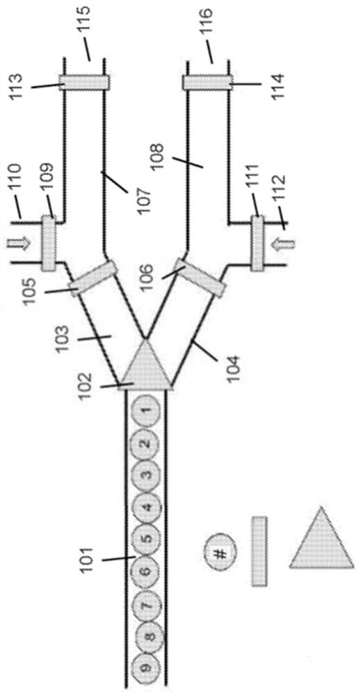
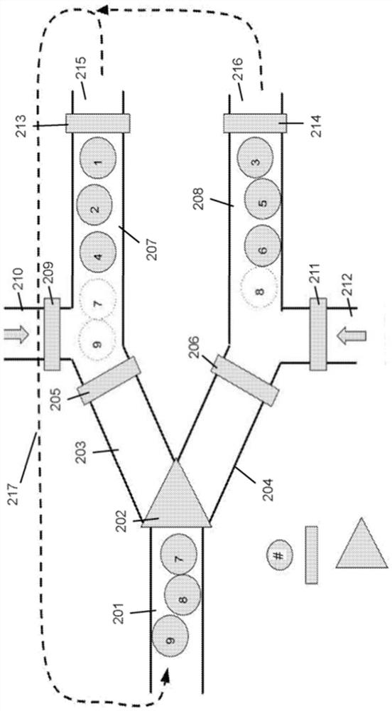
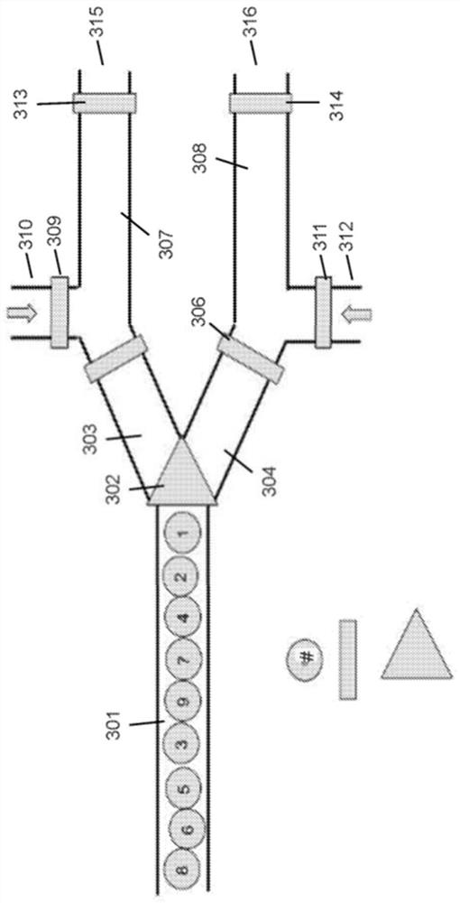
[0525] We constructed a system configured to perform the loading, holding, and manipulation of cells as an example of position encoding in a microfluidic device. The system includes a fluid network and a flow control system that controls the flow of fluid through the network, such as Figure 14 shown. The fluidic network consisted of fused silica capillaries (363um OD, 50um ID, Molex), capillary connectors (CapTight connectors, LabSmith) and custom connectors.

[0526] The bead-containing portion of the network begins with a feed channel 1405, which acts as both a loading channel and a reservoir for beads prior to rearrangement of the beads. This channel is connected to the main channel 1410 by a custom T-connector 1406, which acts as a bead spacer. The two branch channels 1412, 1420 are connected to the main channel by additional T-connectors configured to act as bead spacers. The beads can be distributed and retained in these ...

Embodiment 2

[0531] Position Encoding Device - Bead Spacer

[0532] We first manually loaded a set of highly monodisperse 40 μm beads into the feeder channel 1405, covered the channel input with a bead stopper 1404, and then connected the other end of the bead stopper to the channel’s fluidic control line 1403. In the main channel towards the top side of the main channels 1410 , 1418 , 1426 and through the container 1416 and the main channel container 1417 pressure is applied to the feed channel.

[0533] The beads are fed through the feeder channel in a stacked fashion. When adjoining beads reach the T-connector, the lateral flow creates separation between the beads as they enter the main channel 1410.

[0534] Snapshot images of films of beads separated using T-connectors such as Figure 23 shown. We developed a bead spacer to address the challenges of manipulating beads in a stacked state (i.e., the risk of clogging and loss of positional encoding when channel dimensions change, and ...


PUM

PropertyMeasurementUnit
diameteraaaaaaaaaa
diameteraaaaaaaaaa
diameteraaaaaaaaaa

Abstract

Embodiments relate to methods and compositions useful for routing and tracking multiple mobile units within a microfluidic device. Mobile units may be routed through a plurality of chemical environments, and the mobile units may be tracked to determine the path and / or environments that the mobile units have routed through. Mobile units may be routed in accordance with a predetermined algorithm. Mobile units may be routed through microfluidic devices in ordered flow. Mobile units routed through the microfluidic device can be used to perform various chemical reactions uniquely associated to the units, including without limitation peptide synthesis, enzymatic gene synthesis and gene assembly.

Description

[0001] CROSS-REFERENCE TO RELATED APPLICATIONS [0002] This application claims are based on US Provisional Application No. 62 / 810,196 filed on February 25, 2019, US Provisional Application No. 62 / 811,506 filed on February 27, 2019, US Provisional Application No. 62 / 811,506 filed on June 19, 2019 Priority to US Provisional Application No. 62 / 863,712 and US Provisional Application No. 62 / 958,153, filed January 7, 2020, all of which are incorporated herein by reference in their entirety. Background technique [0003] In biology, chemistry and other fields, it is often necessary to both create a large number of compounds or products and to evaluate the properties, properties, properties or utility of those products. Historically, individual products were manufactured and characterized in separate containers. Batch-type programs have been developed and published that are capable of producing multiple products at once. However, due to the cost, space requirements and required phy...

Claims


Application Information

Patent Timeline
Patent Type & Authority Applications(China)
IPC IPC(8): B01L3/00C12Q1/68
CPCB01L3/502761B01L3/502715B01L2200/0652B01L2300/0816B01L2300/0864B01L2300/1827B01L7/52C12Q1/6834B01J19/0046C12N15/1031B01J2219/00722B01J2219/00605B01J2219/00286B01J2219/00418B01J2219/00509B01J2219/00585B01J2219/0059B01J2219/0054C12Q2521/514C12Q2565/629B01L3/502753B01L2200/16B01L2300/0663C12Q1/6844C40B50/06
Inventor M·海尔M·洪格尔A·沃阿巴O·E·卡恩
Owner 艾勒根公司
Why Eureka
Try Eureka