Phase demodulation method and system based on full-digital phase shift

An all-digital, phase demodulation technology, applied in measuring devices, instruments, measuring ultrasonic/sonic/infrasonic waves, etc., can solve problems such as signal strength weakening, system measurement deviation, system complexity, etc., to improve signal strength and signal-to-noise ratio , Eliminate system deviation, the effect of simple system

Pending Publication Date: 2021-12-21
孙安
View PDF0 Cites 0 Cited by
  • Summary
  • Abstract
  • Description
  • Claims
  • Application Information

AI Technical Summary

Problems solved by technology

The 3×3 coupler method is a widely used phase demodulation method. Although the demodulation method based on the hardware 3×3 coupler has the advantages of large dynamic range, high response bandwidth, simple structure, and no modulation device, etc. The key problems are: 1) It is difficult to accurately maintain a 120° phase difference at the three output terminals of the 3×3 coupler, which causes system measurement deviation; 2) The system requires additional interference structures, which weakens the signal strength and causes the signal-to-noise ratio to deteriorate; 3 ) requires 3 photodetectors combined with signal analysis hardware for phase demodulation, resulting in complex system, high cost and the introduction of additional system noise

Method used


Image

  • Phase demodulation method and system based on full-digital phase shift
  • Phase demodulation method and system based on full-digital phase shift
  • Phase demodulation method and system based on full-digital phase shift

Examples


Embodiment 1

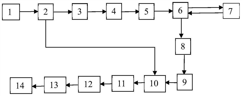
[0056] Combine below figure 1 This embodiment will be specifically described.

[0057] this invention The system includes a narrow-linewidth semiconductor laser light source 1, a first fiber coupler 2, an acousto-optic modulator 3, a signal generator, a first erbium-doped fiber amplifier 4, a first filter 5, a circulator 6, and a second erbium-doped fiber amplifier. Optical fiber amplifier 8 , second filter 9 , second optical fiber coupler 10 , photodetector 11 , data acquisition card 12 , phase demodulation unit 13 and computer 14 . The connection mode of the system is as follows: the output end of the narrow-linewidth semiconductor laser light source 1 is connected to the input end of the first fiber coupler 2, and the first output end of the first fiber coupler 2 is connected to the input end of the acousto-optic modulator 3 in turn, and the acousto-optic modulation The 3 output ports of the device are connected to the 4 input ports of the first erbium-doped fiber amplif...

Embodiment 2

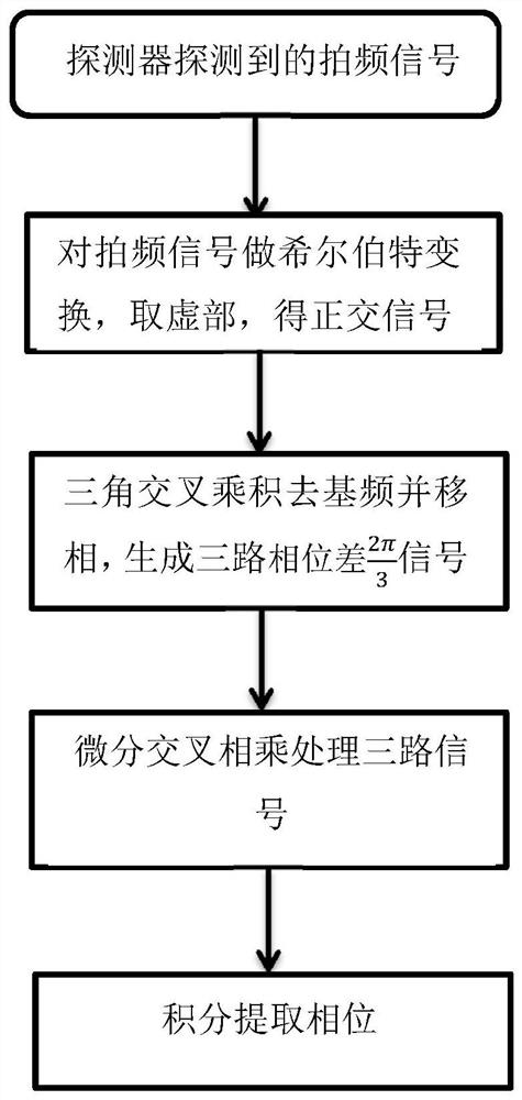
[0061] The present invention also provides a phase demodulation method based on full digital phase shifting, refer to figure 2 ,include:

[0062] Obtain beat frequency signal;

[0063] Filter out the DC component in the beat frequency signal, leaving the AC component containing phase information;

[0064] Perform Hilbert transform on the AC component in the beat frequency signal to obtain the quadrature signal; remove the fundamental frequency in the quadrature signal and perform phase shift to obtain three channels with phase difference The signal; demodulate the three-way signal with phase difference to get the phase information.

[0065] The specific implementation steps of this embodiment are as follows:

[0066] Step 1. Extract the DC component I of the beat frequency signal I(t) detected by the detector L (t). in:

[0067]

[0068] In the formula, I(t) is the real-time intensity of beat frequency signal; E L0 is the amplitude of the local light; ω is the freq...


PUM


Abstract

The invention discloses a phase demodulation method and system based on full-digital phase shift. The phase demodulation method comprises the following steps: acquiring a beat frequency signal; filtering out direct current components in the beat frequency signals, and leaving alternating current components containing phase information; performing Hilbert transform on an alternating current component in the beat frequency signal to obtain an orthogonal signal; removing fundamental frequency in the orthogonal signals, carrying out phase shifting, and obtaining three paths of signals with phase differences; and demodulating the three paths of signals with the phase difference to obtain phase information. The method has the advantages that the phase of the sensing system can be effectively demodulated through a digital algorithm, a plurality of photoelectric detectors do not need to be combined with signal analysis hardware for phase demodulation, the system is simple, the cost is low, and extra system noise cannot be introduced. Besides, the demodulation method can accurately generate three paths of 120-degree phase difference signals and eliminate system deviation, and the method does not need an additional optical fiber interference structure at a demodulation end, so that the signal strength and the signal-to-noise ratio can be effectively improved.

Description

technical field [0001] The invention relates to a fully digital phase-shifting phase demodulation method for a phase-sensitive optical time-domain reflectometer system, which is used for phase-demodulation analysis of coherent photoelectric signals of a phase-sensitive optical time-domain reflectometer system. It can realize the digital demodulation of the phase of the phase-sensitive optical time domain reflectometer system, and then realize the real-time analysis of the distributed optical fiber vibration sensing signal, so as to effectively obtain the external vibration and other information received by the optical fiber. Background technique [0002] Due to the advantages of small size, simple structure, high sensitivity, corrosion resistance and high temperature resistance, and anti-electromagnetic interference, distributed optical fiber sensing technology has become a research hotspot in the field of optical fiber sensing applications at home and abroad. Among them, th...

Claims


Application Information

Patent Timeline
Patent Type & Authority Applications(China)
IPC IPC(8): G01H9/00
CPCG01H9/004
Inventor 孙安吴智深杨阳
Owner 孙安
Why Eureka
Try Eureka