Eureka AIR delivers breakthrough ideas for toughest innovation challenges, trusted by R&D personnel around the world.

Sequential exhaust control method for fuel cell

A fuel cell and control method technology, which is applied in the direction of fuel cell control, fuel cell, fuel cell additives, etc., can solve the problems of long tail valve opening time, inconsistent pressure, fuel cell performance degradation, etc., and improve the utilization rate of hydrogen , prolong the service life and reduce the difference effect

Active Publication Date: 2021-12-28
南京氢创能源科技有限公司 +1
View PDF7 Cites 1 Cited by
  • Summary
  • Abstract
  • Description
  • Claims
  • Application Information

AI Technical Summary

Problems solved by technology

During the operation of the hydrogen treatment system, the most important thing is to control the exhaust valve, including the control of the opening time and interval time of the exhaust valve. If the opening time and interval time of the exhaust valve are not set properly, many problems will occur , such as too high exhaust frequency or too long tail valve opening time, will cause hydrogen waste and bring potential safety risks
However, if the exhaust frequency is too low or the opening time of the exhaust valve is too short, it is easy to cause water blockage or accumulation of impurity gases in some single cells in the fuel cell, causing inconsistencies between single cells (such as single cells) Inconsistent battery voltage, inconsistent water saturation, inconsistent pressure, etc.), resulting in fuel cell performance degradation

Method used


Image

  • Sequential exhaust control method for fuel cell
  • Sequential exhaust control method for fuel cell
  • Sequential exhaust control method for fuel cell

Examples


Embodiment Construction

[0045] The technical solutions of the present invention are further described below with reference to the accompanying drawings and through specific embodiments.

[0046] Among them, the accompanying drawings are only used for exemplary description, and they are only schematic diagrams, not physical drawings, and should not be construed as restrictions on this patent; in order to better illustrate the embodiments of the present invention, some parts of the accompanying drawings will be omitted, The enlargement or reduction does not represent the size of the actual product; it is understandable to those skilled in the art that some well-known structures and their descriptions in the accompanying drawings may be omitted.

[0047] The same or similar numbers in the drawings of the embodiments of the present invention correspond to the same or similar components; in the description of the present invention, it should be understood that if the terms "upper", "lower", "left" and "rig...


PUM


Abstract

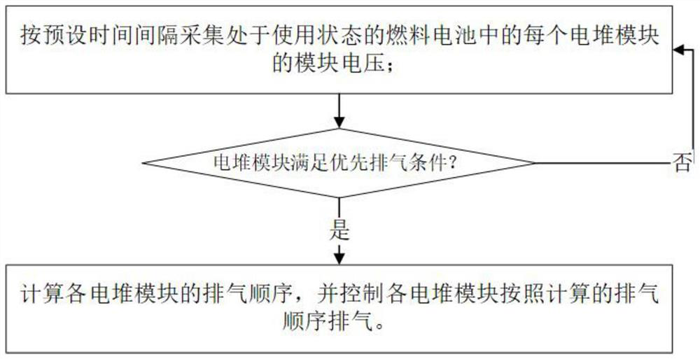
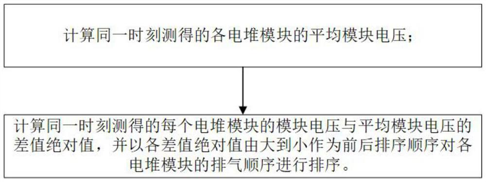
The invention discloses a sequential exhaust control method for a fuel cell. The sequential exhaust control method comprises the following steps: 1) acquiring module voltage of each electric pile module in the fuel cell in a use state according to a preset time interval; 2) according to the measured module voltage, judging whether each galvanic pile module reaches a preferential exhaust condition, if at least one galvanic pile module reaches the preferential exhaust condition, calculating the exhaust sequence of each galvanic pile module, and controlling each galvanic pile module to exhaust according to the calculated exhaust sequence; and if all the stack modules do not meet the preferential exhaust condition, returning to the step 1). According to the invention, reasonable control of the exhaust sequence of each single battery (or an electric pile module formed by at least one single battery) in the fuel cell is realized, and improvement of the hydrogen utilization rate of the fuel cell, reduction of the difference among the single batteries, improvement of the durability of the single batteries and prolonging of the service life of the fuel cell are facilitated.

Description

technical field [0001] The present invention relates to the technical field of fuel cells, in particular to a time-sequential exhaust control method for fuel cells. Background technique [0002] The interior of the fuel cell is divided into an air treatment system, a hydrogen treatment system and a hydrothermal circulation treatment system. The air treatment system provides suitable air for the inside of the cell. The hydrogen treatment system improves the reaction of the fuel to generate energy, and the hydrothermal circulation treatment system converts the reaction inside the cell. The environment is kept within suitable conditions. During the operation of the hydrogen treatment system, the most important thing is the control of the tail exhaust valve, including the control of the opening time and interval time of the tail exhaust valve. If the opening time and interval time of the tail exhaust valve are not set properly, many problems will occur. For example, if the exha...

Claims


Application Information

Patent Timeline
Patent Type & Authority Applications(China)
IPC IPC(8): H01M8/04082H01M8/04089H01M8/04298H01M8/04537H01M8/04746
CPCH01M8/04559H01M8/04753H01M8/04298H01M8/04089H01M8/04201Y02E60/50
Inventor 孙大伟于广伟张欣禹杜文杰黄凌武曹久鹤
Owner 南京氢创能源科技有限公司
Why Eureka
Eureka Blog
Learn More