

Blast burner for manufacturing optical fiber preform
An optical fiber preform and blowtorch technology, used in manufacturing tools, glass manufacturing equipment, etc., can solve the problems of slow mixing speed of raw materials, easy blockage of ejection holes, unstable flame, etc. Stick stable effect
- Summary
- Abstract
- Description
- Claims
- Application Information
AI Technical Summary
Problems solved by technology
Method used
Image

Examples
Embodiment Construction
[0018] The following will clearly and completely describe the technical solutions in the embodiments of the present invention with reference to the accompanying drawings in the embodiments of the present invention. Obviously, the described embodiments are only some, not all, embodiments of the present invention. Based on the embodiments of the present invention, all other embodiments obtained by persons of ordinary skill in the art without making creative efforts belong to the protection scope of the present invention.
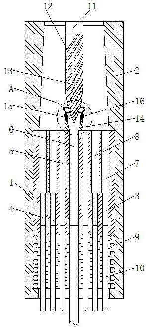
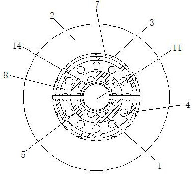
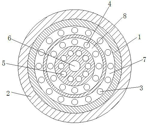
[0019] see Figure 1-3 , a blowtorch for manufacturing optical fiber preforms, comprising a distribution ring 1, the outer movable sleeve of the distribution ring 1 is provided with a lamp cover 2, the outer ring inside the distribution ring 1 is annularly provided with an air hole-3, and the inside of the distribution ring 1 is located at the air hole-1 The inner ring of 3 is provided with air hole 2 4, the inner ring of distribution ring 1 and located at air...
PUM
 Abstract
Description
Claims
Application Information