Metal heat treatment softening annealing treatment device

A metal heat treatment, softening annealing technology, applied in heat treatment furnaces, heat treatment equipment, dry goods processing, etc., can solve the problems of uneven hardness of sealing gaskets, insufficient heating degree, affecting the heating, heat preservation and cooling process of copper sealing gaskets, etc. Avoid copper gasket offset, improve efficiency, avoid the effect of uneven hardness

Inactive Publication Date: 2021-12-31
惠州市先力得金属科技有限公司
View PDF0 Cites 2 Cited by
  • Summary
  • Abstract
  • Description
  • Claims
  • Application Information

AI Technical Summary

Problems solved by technology

[0006] In order to overcome the shortcomings of the prior art that when annealing this type of copper sealing gasket, the contact position between the copper sealing gasket and the tray is not heated enough, which directly affects the heating, heat preservation and cooling process of the copper sealing gasket, resulting in uneven hardness of the sealing gasket after annealing, the present invention Provide a metal heat treatment softening annealing treatment device

Method used


Image

  • Metal heat treatment softening annealing treatment device
  • Metal heat treatment softening annealing treatment device
  • Metal heat treatment softening annealing treatment device

Examples


Embodiment 1

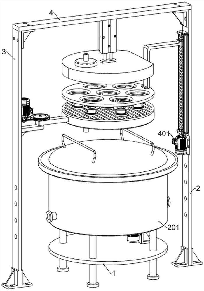
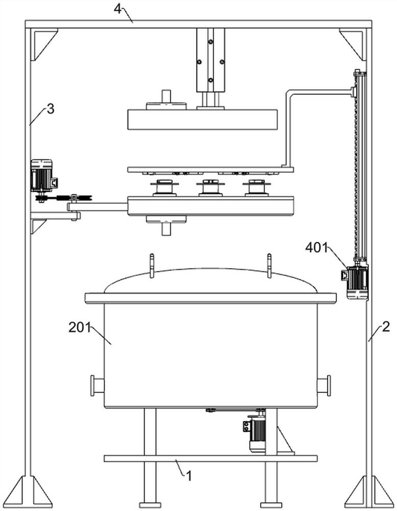
[0034] A metal heat treatment softening annealing treatment device, such as Figure 1-8As shown, it includes a support table 1, a first support frame 2, a second support frame 3, a third support frame 4, an annealing assembly and a first adjustment assembly; the right side of the support table 1 is provided with a first support frame 2; the support table 1. A second support frame 3 is provided on the left; a third support frame 4 is fixedly connected between the upper ends of the first support frame 2 and the second support frame 3; an annealing assembly is installed on the upper part of the support table 1; seven groups of First adjustment component.

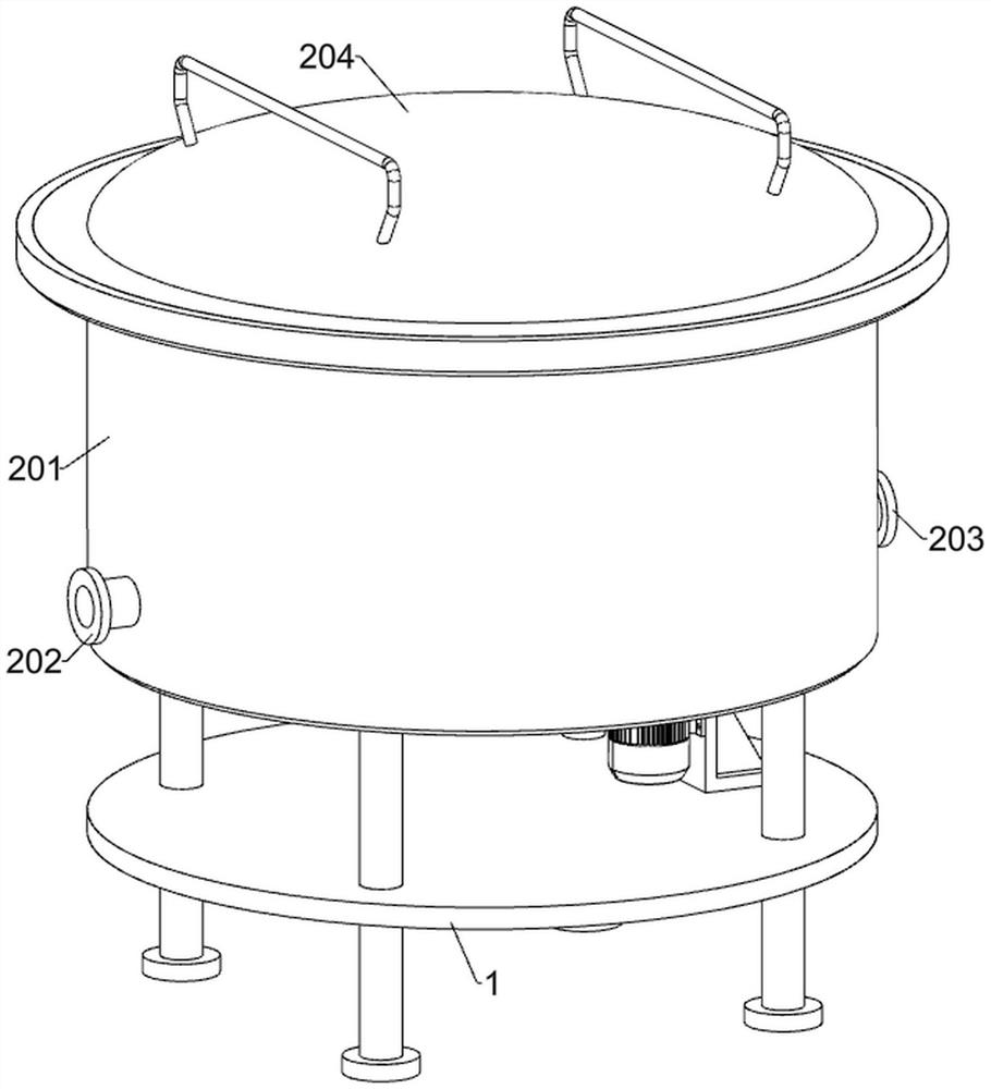
[0035] The annealing assembly includes a first annealing chamber 201, a first joint 202, a second joint 203, a first top cover 204, a first motor 205, a first connecting frame 206, a first guide rod 207, a first screw rod 208, a first A linkage plate 209, the first transmission wheel 2010, the first transmission rod 2011, the ...

Embodiment 2

[0041] On the basis of Example 1, such as figure 1 , Figure 9-11 As shown, a drying assembly is also included. The drying assembly is located under the third support frame 4. The drying assembly includes a second motor 401, a first guide rail 402, a second screw rod 403, a first slider 404, a first The linkage frame 405, the second receiving plate 406, the first telescopic cylinder 407, the first dryer 408, the third motor 409, the first linkage block 4010, the second dryer 4011, the third transmission wheel 4012 and the fourth transmission Wheel 4013; the middle part of the first support frame 2 is fixedly connected with the second motor 401; the upper part of the first support frame 2 is fixedly connected with the first guide rail 402; the middle part of the third support frame 4 is fixedly connected with the first telescopic cylinder 407; the second support frame 3 The upper part is fixedly connected with the third motor 409; the upper output end of the second motor 401 i...

Embodiment 3

[0046] On the basis of Example 2, such as figure 1 , Figure 12-13As shown, it also includes a second adjustment assembly. Seven sets of second adjustment assemblies are fixedly connected to the upper part of the second dryer 4011. The second adjustment assembly includes a first electric turntable 601, a first linkage column 602, and a third linkage block. 603, the first U-shaped block 604, the second limit rod 605, the second spring 606 and the first arc-shaped plate 607; the middle part of the upper surface of the second dryer 4011 is fixed with the first electric turntable 601; the first electric turntable 601 The rotating part is fixedly connected with the first linkage column 602; the middle part of the upper surface of the first linkage column 602 is fixedly connected with the third linkage block 603; the left and right sides of the third linkage block 603 are fixedly connected with a first U-shaped block 604; The middle part of each first U-shaped block 604 is slidingl...


PUM


Abstract

The invention relates to the field of metal heat treatment, in particular to a metal heat treatment softening annealing treatment device. The technical problem to be solved is that the heating degree of the contact position of a copper sealing washer and a tray is insufficient. According to the technical scheme, the metal heat treatment softening annealing treatment device comprises a supporting table, an annealing assembly, first adjusting assemblies and the like, wherein the annealing assembly is installed on the upper part of the supporting table; and the seven sets of first adjusting assemblies are installed on the inner side of the annealing assembly. During use, the copper sealing washer is heated uniformly by adjusting the bearing position of the copper sealing washer, the defect that the hardness of the sealing washer is not uniform after annealing is overcome, meanwhile, the copper sealing washer is prevented from deviating, the copper sealing washer is automatically dried, and meanwhile, cleaning liquid remaining on the bottom face of the outer ring face of the copper sealing washer is automatically removed; and the dried copper sealing washer is synchronously put into a designated position in an annealing furnace, so that the copper sealing washer does not need to be manually taken out and then put into the annealing furnace, and the efficiency is greatly improved.

Description

technical field [0001] The invention relates to the field of metal heat treatment, in particular to a softening annealing device for metal heat treatment. Background technique [0002] Heat treatment refers to a metal thermal processing process in which materials are heated, kept warm and cooled in a solid state to obtain the desired structure and properties. During the progression from the Stone Age to the Bronze and Iron Ages, the role of heat treatment was gradually recognized. [0003] The copper sealing gasket formed by machining needs to be annealed to eliminate residual stress, eliminate work hardening phenomenon, and make it soft to achieve better sealing effect; [0004] In the prior art, when annealing this type of copper sealing gasket, the copper sealing gasket is directly placed on the tray, and then the tray is put into the annealing furnace to be heated and kept for a certain period of time, and then cooled naturally. During this process, the copper sealing g...

Claims


Application Information

Patent Timeline
Patent Type & Authority Applications(China)
IPC IPC(8): C21D1/32C21D9/40C22F1/08F26B11/18F26B25/00F26B25/02F26B25/18
CPCC21D1/32C21D9/40C22F1/08C21D9/0025C21D9/0018F26B11/18F26B25/02F26B25/003F26B25/185
Inventor 邱鹏
Owner 惠州市先力得金属科技有限公司
Why Eureka
Try Eureka