Joint cutting protection device for road and bridge construction

A technology for bridge construction and protective devices, which is applied in the directions of roads, bridges, roads, etc., can solve the problems of generating high temperature, unable to cut the cooling effect of the cutter head, etc., to achieve good cooling and dust removal, easy stability and movement, and increased water spray Effect

Inactive Publication Date: 2021-12-31
HENAN VOCATIONAL & TECHN COLLEGE OF COMM
View PDF1 Cites 2 Cited by
  • Summary
  • Abstract
  • Description
  • Claims
  • Application Information

AI Technical Summary

Problems solved by technology

[0004] However, this device will generate high temperature during cutting, and this device cannot cool down the cutting disc, posing a safety hazard

Method used


Image

  • Joint cutting protection device for road and bridge construction
  • Joint cutting protection device for road and bridge construction
  • Joint cutting protection device for road and bridge construction

Examples


Embodiment 1

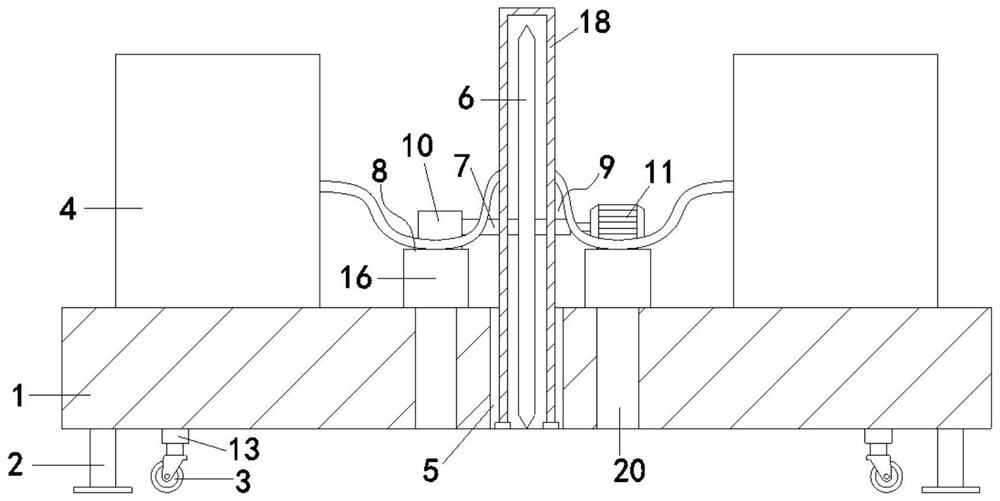
[0032] see Figure 1-6 , the present invention provides a technical solution: a kerf protection device for road and bridge construction, comprising a mobile platform 1, the four corners of the top of the mobile platform 1 are provided with supporting legs 2, and the inner side of the supporting legs 2 is provided with universal wheels 3. A first electric push rod 13 is connected to the top of the wheel 3, and the first electric push rod 13 is fixedly connected to the bottom of the mobile platform 1. A water tank 4 is provided on both sides of the top of the mobile platform 1, and a booster pump is arranged in the water tank 4. Can provide pressure for the nozzle 17, which belongs to the prior art and will not be described in detail. The middle of the mobile platform 1 is longitudinally provided with a through groove 5, and a cutting knife 6 is arranged in the through groove 5. The center of the cutting knife 6 is fixed with a rotating shaft 7, and the rotating shaft 7 The righ...

Embodiment 2

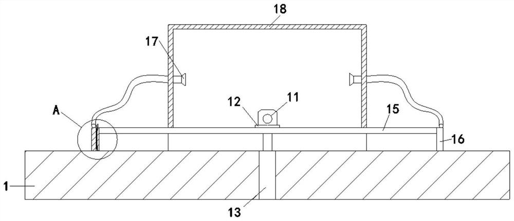
[0040] This embodiment is basically the same as Embodiment 1, the difference is that the bottom of the moving block 10 and the motor 11 is provided with an electric slider 12, and the tops of the first slide 14 and the second slide 15 are longitudinally provided with electric slide rails. The slide block 12 is slidingly connected with the electric slide rail, and the electric slide block 12 and the electric slide rail belong to the prior art, and the sliding of the electric slide block 12 can make the cutting knife 6 move back and forth, so as to facilitate linear cutting on the ground.

[0041] The bottom of lifting protective shell 18 is provided with small-sized mobile roller, and when cutting knife 6 moves back and forth and carries out longitudinal cutting, lifting protective shell 18 can move forward and backward stably thereupon, keeps good protective effect.

[0042] The bottom of the support leg 2 is provided with a fixed piece, which increases the contact area between...


PUM


Abstract

The invention relates to the technical field of roads and bridges, in particular to a joint cutting protection device for road and bridge construction, which comprises a moving platform, water tanks are arranged on two sides of the top of the moving platform, a through groove is longitudinally formed in the middle of the moving platform, a cutting knife is arranged in the through groove, a rotating shaft is fixed at the circle center position of the cutting knife, and a motor is arranged on the right side of the rotating shaft. A moving block is arranged at the left side. A first sliding plate and a second sliding plate are arranged on the left side and the right side of the cutting knife correspondingly, fixing columns are connected to the front ends and the rear ends of the first sliding plate and the second sliding plate correspondingly, and linkage assemblies are arranged in the fixing columns; during use, when a cutting knife continuously moves downwards to cut the ground, a valve ring can be driven to rotate through a linkage assembly, when dust is increased and the temperature rises, the water spraying amount of a spray head is increased, and cooling and dust removal are better performed; and after cutting is completed, the cutting knife moves upwards, the valve ring rotates reversely, the spray head stops spraying water, manual closing is not needed, and the overall good linkage effect is achieved.

Description

technical field [0001] The invention relates to the technical field of roads and bridges, in particular to a kerf protection device for road and bridge construction. Background technique [0002] Road bridges are generally composed of several parts such as roadbed, road surface, bridge, tunnel engineering and traffic engineering facilities. When constructing roads and bridges, it is usually necessary to use devices to slit the road surface, so the slit protection device is required. [0003] Such as patent No. CN212865630U discloses a kind of kerf protection device for road and bridge construction, including slitting machine and cutter head protection mechanism; It is used to cut the road surface; the cutter head protection mechanism includes a protective cover and a water spray dust reduction mechanism; the protective cover includes a first protective cover and a second protective cover; the first protective cover is slidingly sleeved outside the cutter head shell; the bot...

Claims


Application Information

Patent Timeline
Patent Type & Authority Applications(China)
IPC IPC(8): E01D21/00E01C23/09B08B3/04B08B15/04B23Q11/10
CPCE01D21/00E01C23/0933B08B3/04B08B15/04B23Q11/10
Inventor 张艳艳郭朋朋王菊蕊张永霞贾悦
Owner HENAN VOCATIONAL & TECHN COLLEGE OF COMM
Why Eureka
Try Eureka