System for simultaneously measuring five-degree-of-freedom motion errors of rotating shaft

A motion error and rotary axis technology, applied in the system field of simultaneous measurement of the motion error of the rotary axis with five degrees of freedom, can solve the problems of servo rotation error, unfavorable error compensation, large environmental impact, etc., to avoid the introduction of related errors and applicability Strong, improve the effect of measurement accuracy

Pending Publication Date: 2021-12-31
BEIJING JIAOTONG UNIV
View PDF8 Cites 1 Cited by
  • Summary
  • Abstract
  • Description
  • Claims
  • Application Information

AI Technical Summary

Problems solved by technology

The above-mentioned optical measurement methods have high measurement accuracy, but are greatly affected by the environment. Among them, some methods require multiple installations, while others require a servo rotary system, which leads to the introduction of various errors
The non-optical measurement methods such as ballbar and R-test for measuring the error of the rotation axis have the advantages of simple measurement equipment and convenient use, but these optical measurement methods are basically indirect measurements, which need to be separated by complex decoupling calculations. The error of the degree of freedom is not conducive to error compensation
[0003] Patent CN106595480 discloses a laser measurement system and method for measuring the geometric error of the six degrees of freedom of the rotating shaft, which can realize the simultaneous measurement of the geometric error of the six degrees of freedom of the rotating shaft, but this method still needs a servo tracking unit, thereby introducing servo rotation errors and installation errors Wait
[0004] The corner cube is often used to measure the straightness error of the moving target, and the grating is often used to measure the angle error, especially the rotation of the corner cube and the ring grating around the axis of rotational symmetry does not affect the direction of the retroreflected light and the rotational symmetry of the spatial position characteristics, the combination of the two can well measure the multi-degree-of-freedom motion error of the rotating axis, but there is no relevant technical content in the prior art

Method used


Image

  • System for simultaneously measuring five-degree-of-freedom motion errors of rotating shaft
  • System for simultaneously measuring five-degree-of-freedom motion errors of rotating shaft
  • System for simultaneously measuring five-degree-of-freedom motion errors of rotating shaft

Examples


Embodiment 1

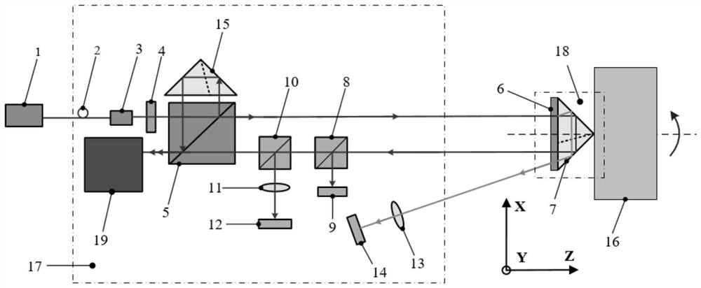
[0054] figure 1 Provided by the present embodiment for a system structure diagram five degrees of freedom movement of the rotary shaft while measuring the error in order to more clearly illustrate the five degrees of freedom to establish a coordinate system O-XYZ embodiment of the present embodiment; measured rotating rotation center axis and Z axis is parallel to the axis, and an annular corner cube circle grating rotationally symmetrical axis is also parallel to the Z-axis, and coincides with the central axis of rotation of the rotating shaft to be measured; five degrees of freedom of the rotating shaft to be measured at this time errors were: translation along the X, Y, Z three directions of the three straightness errors δ X ,δ Y ,δ Z Around the X, Y two inclination angle of rotation of the two coordinate axes error ε X Ε Y .

[0055] Refer figure 1 , The system comprising: an optical path connecting a light source 1, the measuring unit 17 and unit 18 is sensitive to errors.

...

Embodiment 2

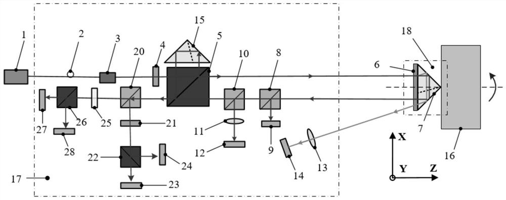
[0078] Figure 4 Provided by the present embodiment for a system structure diagram five degrees of freedom movement of the rotary shaft while measuring the error in order to more clearly illustrate the five degrees of freedom to establish a coordinate system O-XYZ embodiment of the present embodiment; measured rotating rotation center axis and Z axis is parallel to the axis, and an annular corner cube circle grating rotationally symmetrical axis is also parallel to the Z-axis, and coincides with the central axis of rotation of the rotating shaft to be measured; five degrees of freedom of the rotating shaft to be measured at this time errors were: translation along the X, Y, Z three directions of the three straightness errors δ X ,δ Y ,δ Z Around the X, Y two inclination angle of rotation of the two coordinate axes error ε X Ε Y .

[0079] Refer Figure 4 , The system comprising: an optical path connecting a light source 1, the measuring unit 17 and unit 18 is sensitive to errors.

...


PUM


Abstract

The invention provides a system for simultaneously measuring five-degree-of-freedom motion errors of a rotating shaft. The system comprises a light source, a measuring unit and an error sensing unit which are in light path connection. The light source is a laser for emitting laser; the measuring unit is used for processing the laser emitted by the light source, transmitting the laser to the error sensing unit and measuring the five-degree-of-freedom motion error of the rotating shaft according to the diffracted light returned by the error sensing unit; the error sensing unit comprises an annular grating and a first cube-corner prism, the annular grating is fixed to the center position of the inclined face of the first cube-corner prism, the cone center end of the first cube-corner prism is fixed to the center position of the end face of the rotating shaft, and the rotating center axes of the annular grating, the first cube-corner prism and the rotating shaft coincide. And the error sensing unit is used for diffracting and retroreflecting the incident light of the measuring unit. According to the system, simultaneous measurement of five-degree-of-freedom motion errors of the rotating shaft can be realized, and the detection efficiency is greatly improved.

Description

Technical field [0001] The present invention relates to the field of space geometric precision detection, and more particularly to a system for simultaneously measuring the five degree of freedom motion error of the rotating shaft. Background technique [0002] The measurement of the multi-freedom motion error of the rotating shaft mainly includes a non-optical measurement method measured by a rotating shaft error measurement based on laser interference, diffraction, colonization, and geometric optical or other optical measurement method, and a non-optical measurement method measured by a rotary axis error through a club, R-Test or the like. . The above-mentioned optical measurement method has a high measurement accuracy, but is larger than the environmental impact, where some methods need to be installed multiple times, and some require a servo rotary system, resulting in a variety of errors. The non-optical measurement method of the rotating shaft error measurement has the adva...

Claims


Application Information

Patent Timeline
Patent Type & Authority Applications(China)
IPC IPC(8): G01B11/00
CPCG01B11/00
Inventor 李家琨张海峰冯其波伍李鸿马栋丁要文
Owner BEIJING JIAOTONG UNIV
Why Eureka
Try Eureka