Direct sequence spread spectrum signal time-frequency two-dimensional interpolation precise estimation method
A time-frequency two-dimensional, direct-spread signal technology, used in transmission systems, electrical components, etc., can solve the problems of insufficient carrier Doppler frequency and pseudo-code phase estimation accuracy, and achieve the effect of ensuring the acquisition speed and achieving simplicity.
- Summary
- Abstract
- Description
- Claims
- Application Information
AI Technical Summary
Problems solved by technology
Method used
Image
Examples
Embodiment 1
[0098] This embodiment illustrates the structural block diagram of applying the "a method for time-frequency two-dimensional interpolation and precise estimation of direct-spread signal" of the present invention to large frequency offset and low signal-to-noise ratio. In this embodiment, the radio frequency is f RF =2.2GHz, the period of the pseudo-code is 1023, and the chip rate is R cp = 3.069Mcps at a data rate of R D =2kbps, take the correlation time length as 1 pseudo-code period, and the carrier Doppler frequency as f d ∈(-200kHz,200kHz) as an example, by figure 1 It can be seen that the signal received by the receiver antenna is down-converted and sampled by the RF front-end, and then the frequency is searched in parallel, and the result is output to the FFT module. Correlation calculations are performed on the FFT results of the local pseudo-code sequence, and the signal-to-noise ratio is accumulated through the non-coherent accumulation module. After processing by t...
Embodiment 2
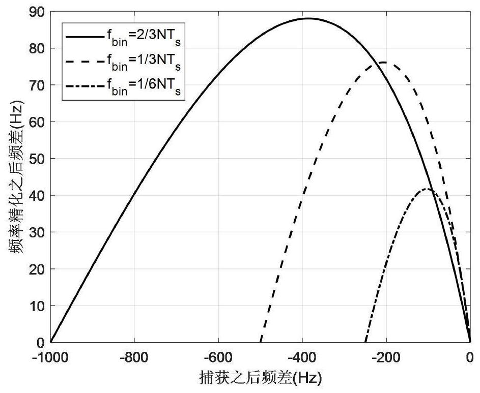
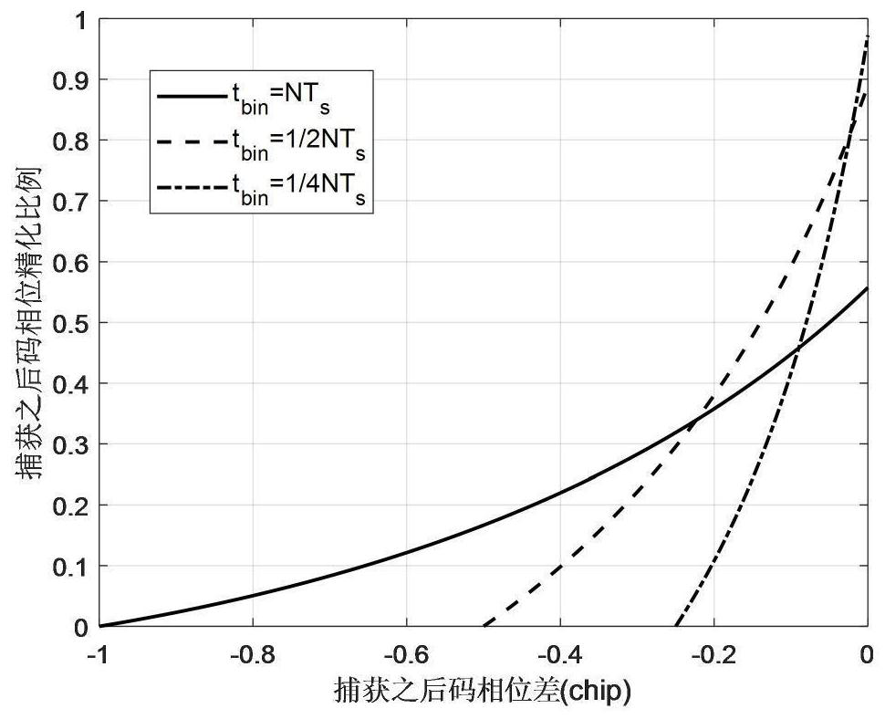
[0100] According to the parameters described in Embodiment 1, this embodiment specifically elaborates the time-frequency two-dimensional refined estimation results after performing steps 1 to 8 of the present invention. The results in the frequency domain are as follows figure 2 As shown, the time domain results are as image 3 shown;
[0101] figure 2 In , the abscissa represents the frequency difference after capture, and its unit is Hz; the ordinate represents the frequency difference after frequency refinement, and its unit is Hz;
[0102] from figure 2 It can be seen from the figure that in this embodiment, the maximum frequency difference after capture can reach 1kHz. After the carrier Doppler frequency is refined by this method, the maximum residual frequency difference does not exceed 90Hz, which greatly optimizes the frequency error after capture. , which is more conducive to the subsequent carrier tracking loop to quickly and stably lock the signal.
[0103] ...
PUM
 Abstract
Description
Claims
Application Information
 - R&D
- Intellectual Property
- Life Sciences
- Materials
- Tech Scout
- Unparalleled Data Quality
- Higher Quality Content
- 60% Fewer Hallucinations
Browse by: Latest US Patents, China's latest patents, Technical Efficacy Thesaurus, Application Domain, Technology Topic, Popular Technical Reports.
© 2025 PatSnap. All rights reserved.Legal|Privacy policy|Modern Slavery Act Transparency Statement|Sitemap|About US| Contact US: help@patsnap.com


