
Method for determining CT positioning center

An isocenter and CT image technology, applied in the field of determining the CT positioning center, can solve the problems of increasing the number of patients exposed to radiation, increasing medical resources, and increasing the economic burden of patients, so as to reduce the number of times exposed to radiation, save medical resources, reduce The effect of treatment costs

Pending Publication Date: 2022-01-07
SICHUAN CANCER HOSPITAL
View PDF0 Cites 0 Cited by
  • Summary
  • Abstract
  • Description
  • Claims
  • Application Information

AI Technical Summary

Problems solved by technology

[0006] The present invention aims to solve the problem that in the current radiotherapy process, when performing CT positioning, the medical personnel do not know the position of the isocenter, and can only roughly set the CT positioning center based on experience, so that the position difference between the CT positioning center and the isocenter is large And uncertain, leading to the need to add a set-up link for verification in the existing radiation therapy process, which leads to the consumption of more medical resources, makes patients face longer waiting periods, increases the number of times patients are irradiated, and increases patient economics. To deal with problems such as burden, a CT positioning method is provided, which can not only effectively ensure that the CT positioning center is very close to the isocenter or coincides with the isocenter, but also can omit the positioning link during the radiotherapy process. The main ideas are:

Method used


Image

  • Method for determining CT positioning center
  • Method for determining CT positioning center
  • Method for determining CT positioning center

Examples


Embodiment 1

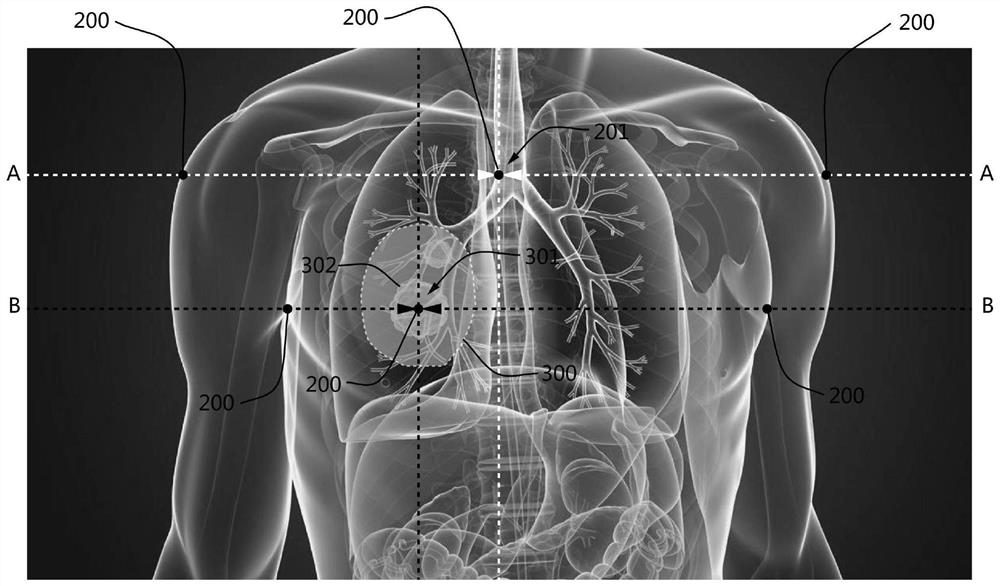
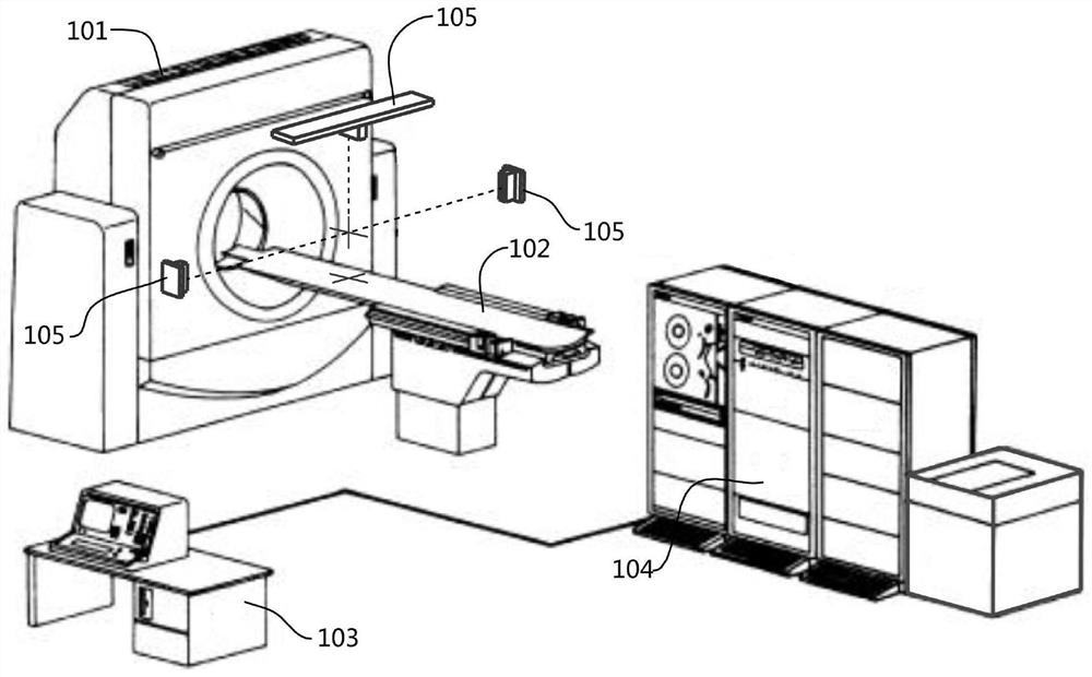
[0034] see figure 1 , a method for determining the center of CT positioning is provided in this embodiment. In order to realize the CT positioning method, a set of CT simulator (or CT simulation system) cooperating with it is provided. The CT simulator mainly plays a role in radiation therapy. Functions such as tumor localization, normal tissue or organ localization, treatment plan design, calculation of measurement distribution, simulation of treatment plan, evaluation of curative effect, etc., in this embodiment, the CT simulator can be an existing CT simulator, In a preferred embodiment, the CT simulator may include a CT simulation positioning machine 101, a treatment couch 102, a computer console 103, a simulator central workstation 104 (or called a simulator server, a computer, a computer system) and a three-dimensional laser positioning machine. system 105, such as figure 2 As shown, the computer console 103, CT simulation positioning machine 101, treatment couch 102, ...


PUM

PropertyMeasurementUnit
Diameteraaaaaaaaaa

Abstract

The invention relates to a method for determining a CT positioning center. The method comprises the following steps of: step 1, when CT positioning is executed, firstly performing CT scanning on a patient to obtain a current CT image of the patient; step 2, identifying and sketching a tumor target area from the CT image, and calculating an isocenter of the tumor target area; and step 3, transmitting coordinates of the isocenter to a three-dimensional laser positioning system, performing isocenter projection on the body surface of the patient by utilizing the three-dimensional laser positioning system, and setting CT marking points at a laser incident point of the body surface of the patient and / or a laser incident point of a body position fixator. According to the method, the CT positioning center can be ensured to be always positioned at a position very close to the isocenter or overlapped with the isocenter; the method is simple, and a positioning link does not need to be added in the radiotherapy process for verification, so that medical resources can be saved, the waiting period of the patient can be shortened, the radiotherapy efficiency can be improved, the number of times of radiation on the patient can be reduced, and the treatment cost of the patient can be reduced.

Description

technical field [0001] The invention relates to the technical field of radiotherapy, in particular to a method for determining a CT positioning center. Background technique [0002] Radiation therapy, referred to as radiotherapy, is a local treatment method that uses radiation to treat tumors. Commonly used radiation includes α, β, and γ-rays produced by radioisotopes and x-rays, electron beams, and protons produced by various x-ray therapy machines or accelerators. beam and other particle beams, etc.; the radiotherapy process is to use radiation to irradiate the lesion, through the biological effects of radiation on human tissues, to achieve the purpose of killing cancer tissue, destroying cancer tissue, and shrinking it. In recent years, radiotherapy has The role and status of tumor therapy have become increasingly prominent, and it has become one of the main means of treating malignant tumors. Two-thirds of all malignant tumor patients need radiotherapy. [0003] In th...

Claims


Application Information

Patent Timeline
IPC IPC(8): A61N5/10
CPCA61N5/1001A61N5/1049A61N5/103A61N2005/1054A61N2005/1097A61N2005/105
Inventor 李林涛王先良比确子拉王培郎锦义路顺康盛伟黎杰张德康
Owner SICHUAN CANCER HOSPITAL
Learn More