
Gas-liquid phase separation spray pipe device used for plasma spraying physical vapor deposition

A technology of physical vapor deposition and plasma spray gun, which is applied in coating, fusion spraying, metal material coating process, etc., can solve the problems of expensive replacement cost, expensive operation cost, and complicated spraying process, and achieve energy and powder utilization rate High, good economic benefits, the effect of high gas phase content

Pending Publication Date: 2022-01-11
SICHUAN UNIV
View PDF0 Cites 0 Cited by
  • Summary
  • Abstract
  • Description
  • Claims
  • Application Information

AI Technical Summary

Problems solved by technology

[0004] However, the current plasma spraying physical vapor deposition technology and equipment are facing the following problems: 1) Spraying needs to be carried out in an ultra-low pressure vacuum tank, the operating cost is expensive, and the spraying of large parts is difficult to achieve; 2) The requirements for high current and high power The electrode of the spray gun is ablated rapidly, and the replacement cost is expensive; 3) The energy and powder utilization rate of the spray gun are very low, and the energy used by powder gasification actually only accounts for 1%-5% of the total power of the spray gun, and most of the heat of the jet is consumed Scattered outside; in addition, the special powder is expensive, and the powder deposition efficiency is less than half of the total powder input; 4) The spraying process is complicated, and the coating quality is difficult to guarantee, even if a higher-power spray gun is used, it is difficult to ensure the input powder Therefore, the coating is often mixed with molten, semi-fused and unfused powder particles, which reduces the quality and repeatability of the coating, making it difficult to prepare a thermal barrier coating with a pure gas phase structure.

Method used


Image

  • Gas-liquid phase separation spray pipe device used for plasma spraying physical vapor deposition
  • Gas-liquid phase separation spray pipe device used for plasma spraying physical vapor deposition

Examples


Embodiment Construction

[0020] The above and other objects, features and advantages of the present invention will be more apparent through the following description of the embodiments of the present invention with reference to the accompanying drawings. The present invention is described below based on the embodiments, and those skilled in the art should understand that the drawings provided here are for illustration purposes, and the drawings are not necessarily drawn to scale.

[0021] Unless the context clearly requires, throughout the specification and claims, "comprises", "comprises" and similar words should be interpreted in an inclusive sense rather than an exclusive or exhaustive meaning; that is, "including but not limited to" meaning.

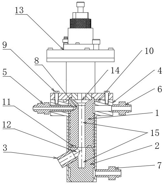
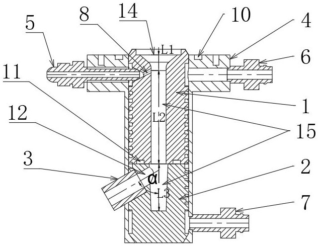
[0022] Such as figure 1As shown, the present invention discloses a gas-liquid phase separation nozzle device for plasma spraying physical vapor deposition, comprising an upper graphite nozzle 1, a lower graphite crucible 2, an outlet graphite short nozzle 3...


PUM

PropertyMeasurementUnit
heightaaaaaaaaaa

Abstract

The invention provides a gas-liquid phase separation spray pipe device for plasma spraying physical vapor deposition. The gas-liquid phase separation spray pipe device comprises an upper graphite spray pipe, a lower graphite crucible, an outlet graphite short spray pipe, an outer sleeve, a powder feeding pipe, a cooling gas inlet pipe and a cooling gas outlet pipe. The spray pipe device is coaxially connected with a plasma spray gun and is vertically placed, a center flow channel coaxially communicating with an outlet of the spray gun and an inclined outlet forming a certain included angle are formed in the interior of a spray pipe, gas-phase components of powder in jet flow are separated from liquid-phase powder and solid-phase powder by changing the movement direction of the jet flow, liquid-phase and solid-phase powder collected at the bottom is continuously heated and gasified, and a thermal barrier coating of a pure gas phase structure is prepared. The device has the advantages that the structure is simple, the energy and powder utilization rate is high, the requirements for the powder, the spray gun and the spraying environment are low, and the thermal barrier coating of the pure gas phase structure can be prepared even under the conditions of the atmospheric environment and the low-power plasma spray gun.

Description

technical field [0001] The invention belongs to the technical field of plasma spraying physical vapor deposition, in particular to a gas-liquid phase separation nozzle device for plasma spraying physical vapor deposition. Background technique [0002] Compared with the layered structure thermal barrier coating prepared by traditional atmospheric plasma spraying, which is formed by stacking molten and semi-fused powders, plasma spraying physical vapor deposition can prepare a columnar structure thermal barrier coating with a higher gas content. It has better thermal shock resistance and higher service life. More importantly, because the gasified powder in the jet is light in weight, it can be wrapped in the jet to achieve wrapping, and can realize non-line-of-sight deposition coatings on the surface of workpieces with complex shapes. This technology has become an international thermal spraying and thermal spraying technology. Research hotspots and development directions in t...

Claims


Application Information

Patent Timeline
Patent Type & Authority Applications(China)
IPC IPC(8): C23C4/134
CPCC23C4/134
Inventor 刘方圆姚进余德平刘宇马力超
Owner SICHUAN UNIV
Learn More