Double-end DDQ type three-phase wireless dynamic charging system for electric vehicle

A dynamic charging, electric vehicle technology, applied in electric vehicle charging technology, electric vehicles, charging stations, etc., can solve the problems of low power conversion efficiency, decreased power conversion efficiency, low coupling coefficient, etc., to improve power conversion efficiency, reduce Reduced charging efficiency and reduced effect of power supply cross-coupling

Pending Publication Date: 2022-01-11
SHENZHEN POLYTECHNIC
View PDF4 Cites 0 Cited by
  • Summary
  • Abstract
  • Description
  • Claims
  • Application Information

AI Technical Summary

Problems solved by technology

It overcomes the disadvantages of low coupling coefficient and poor anti-horizontal offset characteristics of traditional circular coils and flux tube coils, but due to structural limitations, there are shortcomings of cross-coupling in practical applications, which will reduce power conversion efficiency. Reduced, and there are also characteristics such as weak anti-offset characteristics
In addition, in the existing electric vehicle wireless charging system, the size of the primary transmitting coil and the secondary receiving coil are basically the same. In this way, the electric vehicle is charged at rest or during driving, and the primary coil and the secondary coil are easily connected. Offset occurs, which in turn will lead to a decrease in the efficiency of power conversion, and the power transmitted by the system is limited
Finally, the existing wireless charging systems for electric vehicles all use 220V AC power supply. 220V AC power supply has the problems of high charging cost and relatively low power conversion efficiency, so it will more or less affect the development of electric vehicle charging systems. to restrict

Method used


Image

  • Double-end DDQ type three-phase wireless dynamic charging system for electric vehicle
  • Double-end DDQ type three-phase wireless dynamic charging system for electric vehicle
  • Double-end DDQ type three-phase wireless dynamic charging system for electric vehicle

Examples


Embodiment Construction

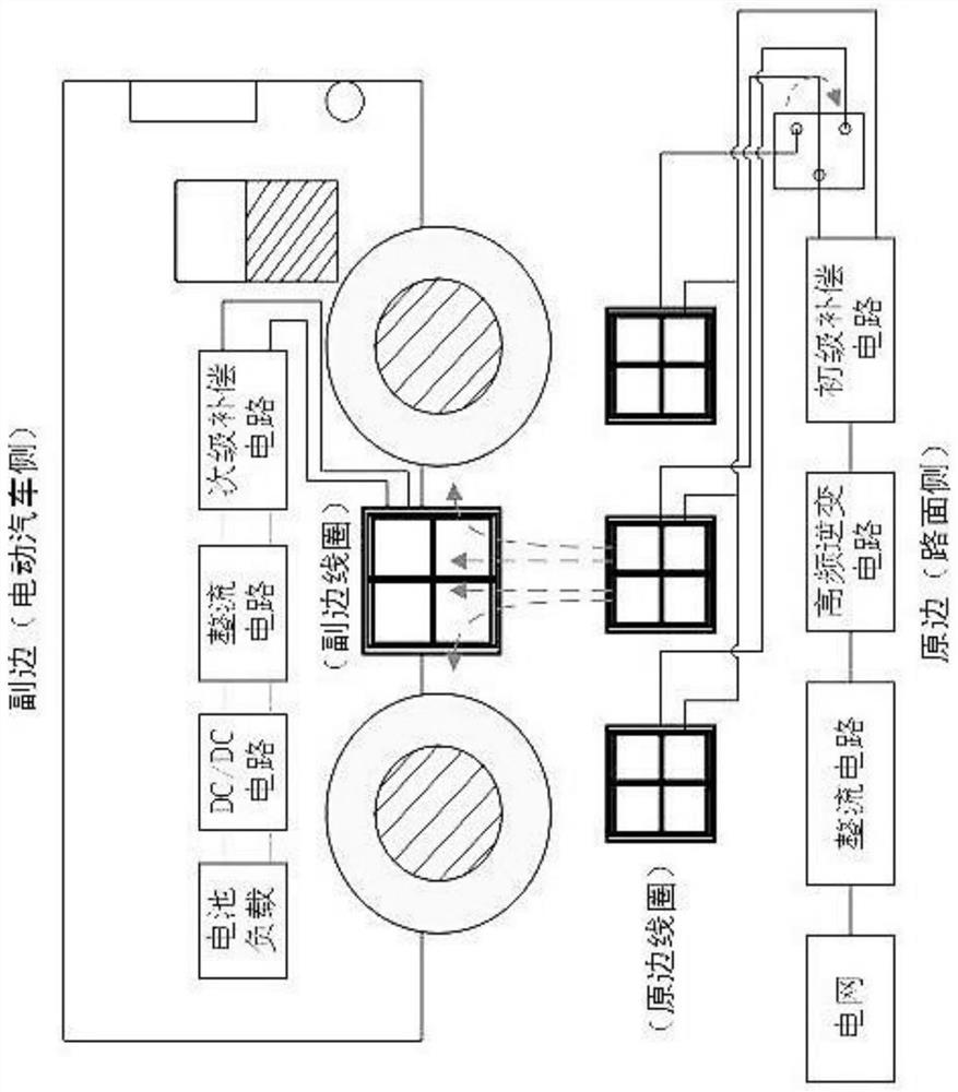
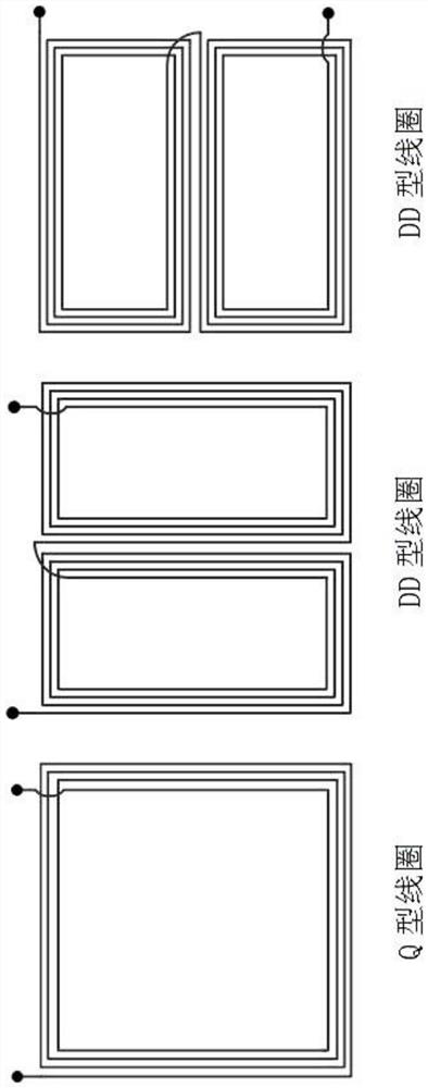
[0017] figure 1 , 2 , 3 shown in 3, an electric vehicle dual-end DDQ three-phase wireless dynamic charging system, including the rectifier circuit, inverter and primary compensation circuit, the original edge coil, and the sub-coil, secondary compensation of the receiving end on the vehicle. And the rectifier circuit, the DC / DC circuit, the original side is mounted on the ground, the secondary side is attached to the lower end of the vehicle; the original edge coil and the secondary coil have a set of Q-type coils, two sets of DD coils, original edge coils, and Q-shaped coil of the secondary coil, the first set of DD coils, the second set of DD coils, respectively, to the second set of DD coils and the first group of the original edge coil and the secondary coil, respectively, the original edge coil and the secondary coil, respectively. The DD coil is 90 ° distribution; the Q-shaped coil of the original edge coil, the DD coil, and the secondary coil of the secondary coil, and t...


PUM


Abstract

A double-end DDQ type three-phase wireless dynamic charging system for an electric automobile comprises a primary side rectifying circuit, an inversion and primary compensation circuit, a primary side coil, a receiving end secondary side coil on the automobile, a secondary compensation and rectifying circuit and a DC/DC circuit, which are electrically connected. The primary side coil and the secondary side coil are respectively provided with a group of Q-type coils and two groups of DD coils, the Q-type coils, the first group of DD coils and the second group of DD coils of the primary side coil and the secondary side coil are respectively wound on iron cores of the primary side coil and the secondary side coil, and the second group of DD coils and the first group of DD coils of the primary side coil and the secondary side coil are distributed at 90 degrees; and the size ratio of the Q-type coil and the DD coil of the primary side coil to the size ratio of the Q-type coil and the DD coil of the secondary side coil is 1: 2. According to the invention, the charging cost is reduced, the power supply conversion efficiency is improved, the anti-offset characteristic of the whole equipment is enhanced, the reduction of the charging efficiency caused by horizontal offset is reduced, the cross coupling of the power supply is effectively reduced, and the transmission power of electric energy is improved.

Description

Technical field [0001] The present invention relates to the technical field of electric vehicle aids, in particular, an electric vehicle double-end DDQ three-phase wireless dynamic charging system. Background technique [0002] Electric cars due to energy saving and environmental protection, applications are increasingly widely used, and the construction of the corresponding electric vehicle charging station is increasing. The existing electric vehicle charging method generally uses a wired charging method. In recent years, with the development of radio energy transmission technology, the statically wireless charging technology based on magnetic field coupling electric vehicles (hereinafter referred to as wireless charging system) has received more and more attention, compared to traditional wired charging systems, wireless The charging system has no electrical connection, which has the advantages of convenient operation, low maintenance cost, waterproof and dustproof, and can re...

Claims


Application Information

Patent Timeline
Patent Type & Authority Applications(China)
IPC IPC(8): H02J50/12H02J7/00B60L53/12
CPCH02J50/12H02J7/00B60L53/12Y02T10/70Y02T10/72Y02T10/7072Y02T90/14
Inventor 唐丽静刘赫林鸿徐赵文徐小野
Owner SHENZHEN POLYTECHNIC
Why Eureka
Try Eureka