Circulating drying machine for compressed air

A compressed air and suction dryer technology, applied in gas treatment, dispersed particle separation, membrane technology, etc., can solve the problems of different degrees of failure, waste of compressed air, affecting work efficiency, etc., to increase dryness, reduce losses, and prolong The effect of age

Inactive Publication Date: 2022-01-18
周波
View PDF0 Cites 0 Cited by
  • Summary
  • Abstract
  • Description
  • Claims
  • Application Information

AI Technical Summary

Problems solved by technology

[0003] First, the structure of the adsorption dryer is a double-tower type. The compressed air first flows through the adsorbent bed from the bottom to the top of the drying tower A, and the dried air is discharged from the upper pipe system. A small amount of dried air (about 7%- 12%) is decompressed through the regeneration gas regulating valve of the upper piping system and enters the heater for heating. This part of hot air (called regeneration gas) enters the drying tank B from top to bottom, and decomposes and regenerates the adsorbent in the drying tank B. To restore the drying capacity of the adsorbent, the two are used alternately, so that the adsorbent in the middle and lower parts of the two tanks is first in contact with the compressed air with a large water content and dried, causing the adsorbent in the middle and lower part to reach the moisture absorption limit first , loses its effect. Similarly, the regeneration gas first dries the middle and upper adsorbents from top to bottom. When the regeneration gas reaches the bottom, it already contains a certain amount of water, which cannot make the middle and lower adsorbents recover quickly, which greatly prolongs the drying process. At the same time, the compressed air after drying is greatly wasted, resulting in a waste of energy
[0004] Second, the adsorbent in the drying tank has different degrees of failure due to different degrees of moisture absorption. In order to ensure the drying quality of the compressed air, once more than one-third of the adsorbent fails or after a certain period of use, the drying tank needs to be replaced. Recovery greatly affects work efficiency. At the same time, in the long-term use process, some adsorbents are completely invalid, and all adsorbents need to be replaced, resulting in waste of cost.

Method used


Image

  • Circulating drying machine for compressed air
  • Circulating drying machine for compressed air
  • Circulating drying machine for compressed air

Examples


Embodiment Construction

[0021] The following will clearly and completely describe the technical solutions in the embodiments of the present invention with reference to the accompanying drawings in the embodiments of the present invention. Obviously, the described embodiments are only some, not all, embodiments of the present invention. Based on the embodiments of the present invention, all other embodiments obtained by persons of ordinary skill in the art without making creative efforts belong to the protection scope of the present invention.

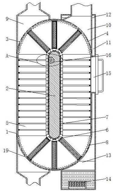
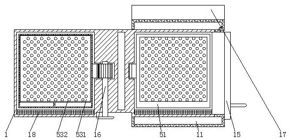
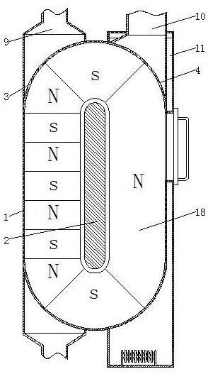
[0022] see Figure 1-5 , a kind of circulation drying machine for compressed air, comprising a fixed box 1 and a circulating air pipe 17, the middle part of the inner cavity of the fixed box 1 is fixedly equipped with a middle partition 2, and the middle partition 2 divides the inner cavity of the fixed box 1 into left and right two The top of the left part of the fixed box 1 is evenly provided with a compressed gas outlet 3, the bottom of the left part of the...


PUM


Abstract

The invention belongs to the technical field of air drying, and discloses a circulating drying machine for compressed air. The circulating drying machine comprises a fixed box and a circulating air pipe; a middle partition plate is fixedly mounted in the middle of an inner cavity of the fixed box. Through an adsorption device, the compressed air enters the fixed box from a compressed air inlet and sequentially penetrates through a movable baffle and an inner box to meet an adsorbent; the adsorbent adsorbs moisture contained in the compressed air, and meanwhile the compressed air pushes the adsorption device upwards to enable the adsorption device to rotate clockwise; the adsorbent can be circularly and uniformly used, a part of the adsorbent is prevented from being in continuous contact with compressed air with high water content and being overused, the service life of the adsorbent is prolonged; and in the rotation process of the adsorption device, due to the fact that the adsorbent is heated and dried after adsorbing the water in the continuous operation process, the maximum dryness can be continuously kept, the moisture adsorption efficiency is improved, and the dryness of the compressed air is enhanced.

Description

technical field [0001] The invention relates to the technical field of gas drying, in particular to a circulation drying machine for compressed air. Background technique [0002] There is a certain amount of gaseous water in the atmosphere, and affected by factors such as seasons, geographical locations, and climatic conditions, the content of gaseous water is changing all the time. At the same time, compressed air, as an important power source next to electricity, has been It is widely used in petrochemical, metallurgy, national defense and other industries. Air compression and use need to be dried. When the water content value exceeds the maximum limit that the production process can bear, a series of problems will appear. The implementation efficiency of the production process has a serious impact. Most of the existing drying technologies use adsorption drying technology to dry compressed air, such as adsorption dryers, but there are some shortcomings in the use process, ...

Claims


Application Information

Patent Timeline
Patent Type & Authority Applications(China)
IPC IPC(8): B01D53/06B01D53/26
CPCB01D53/06B01D53/261B01D53/0454B01D2259/40088B01D2257/80B01D2258/06
Inventor 周波
Owner 周波
Why Eureka
Try Eureka