
Tunnel waterproof drainage structure and tunnel waterproof drainage method

A drainage structure and tunnel technology, applied in drainage, tunnel, tunnel lining and other directions, can solve the problems of poor drainage, troublesome cleaning, and overflow of water in drainage grooves, so as to prevent road surface water, prevent transmission accidents, and increase drainage efficiency. Effect

Inactive Publication Date: 2022-01-18
崔红玉
View PDF0 Cites 0 Cited by
  • Summary
  • Abstract
  • Description
  • Claims
  • Application Information

AI Technical Summary

Problems solved by technology

[0003] Nowadays, all kinds of garbage and sundries are easy to accumulate inside the tunnel drainage tank, which leads to poor drainage of the drainage tank. It is extremely troublesome, time-consuming and laborious to clean up, and if there is too much water in the drainage tank, if it cannot be discharged in time, it will cause the accumulated water to overflow and damage the road surface. Too much water will affect the driving environment

Method used


Image

  • Tunnel waterproof drainage structure and tunnel waterproof drainage method
  • Tunnel waterproof drainage structure and tunnel waterproof drainage method
  • Tunnel waterproof drainage structure and tunnel waterproof drainage method

Examples


Embodiment Construction

[0033] The following will clearly and completely describe the technical solutions in the embodiments of the present invention with reference to the accompanying drawings in the embodiments of the present invention. Obviously, the described embodiments are only some, not all, embodiments of the present invention. Based on the embodiments of the present invention, all other embodiments obtained by persons of ordinary skill in the art without making creative efforts belong to the protection scope of the present invention.

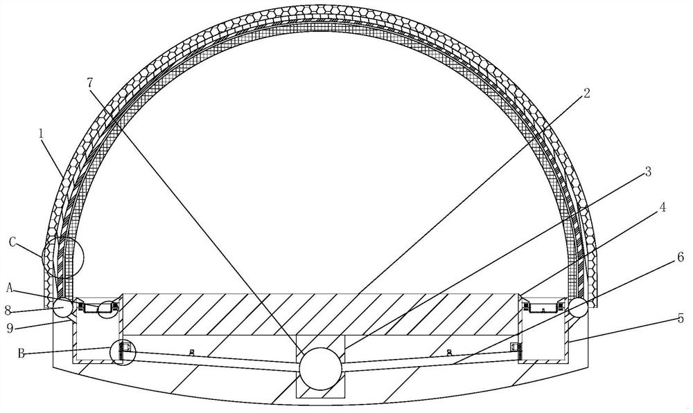
[0034] see Figure 1-8, the present invention provides a tunnel waterproof and drainage structure and a tunnel waterproof and drainage method, including a tunnel and a road surface 2, the tunnel is respectively an initial support layer 1, a support filling layer 33, a protective layer 10, a waterproof layer 34 and a lining concrete from the outside to the inside Layer 35, an annular groove 11 is provided inside the protective layer 10, an annular dead pipe is ...


PUM


Abstract

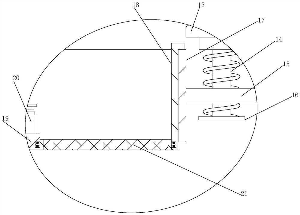
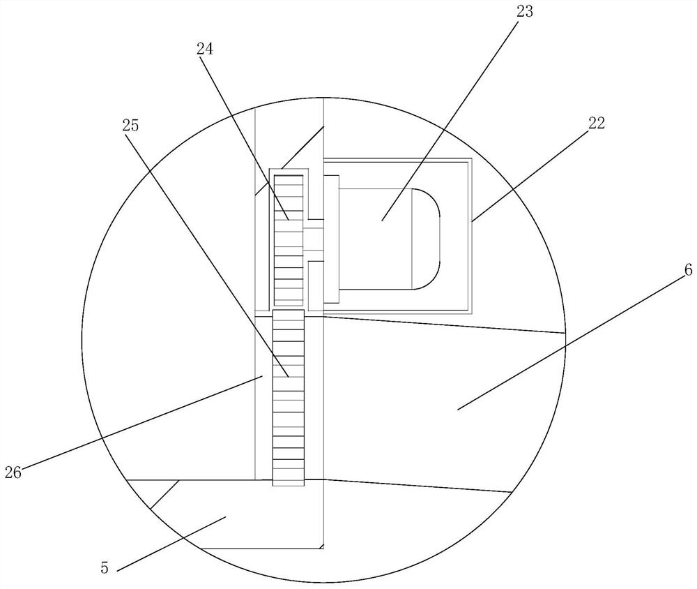
The invention relates to the technical field of tunnel waterproof drainage, and particularly relates to a tunnel waterproof drainage structure and a tunnel waterproof drainage method. The tunnel waterproof drainage structure comprises a tunnel and a road surface, wherein the tunnel is provided with a primary supporting layer, a supporting filling layer, a protective layer, a waterproof layer and a lining concrete layer, an annular groove is formed in the protective layer, an annular blind pipe is arranged in the annular groove, and a drainage groove is formed in one side of the road surface. According to the tunnel waterproof drainage structure and the tunnel waterproof drainage method, a cleaning assembly and a drainage assembly are arranged, when water flow flows into the drainage groove, garbage can be prevented from falling into the bottom of the drainage groove through a filter screen in a movable frame, so that the garbage is stored in the movable frame; when the garbage needs to be cleaned, the movable frame is taken out from the interior of a fixed frame through a pull plate at the top of a telescopic rod, so that the garbage in the movable frame can be conveniently taken out for cleaning; and a rotating cylinder is driven to rotate through a servo motor, and then a central shaft and blades in the rotating cylinder are driven to rotate, so that the spiral blades accelerate the flow of the water flow, the drainage efficiency of the drainage groove is improved, and water accumulation on the road surface is prevented.

Description

technical field [0001] The invention relates to the technical field of tunnel waterproof and drainage, in particular to a tunnel waterproof and drainage structure and a tunnel waterproof and drainage method. Background technique [0002] Tunnel waterproofing and drainage refers to the waterproof and drainage measures taken to ensure that the tunnel building will not cause damage due to water leakage, endanger driving safety, corrode equipment in the tunnel, and reduce the service life of the structure. It is a comprehensive work involving factors such as terrain, climate, engineering strata and hydrogeology, structural schemes, construction methods, and material properties; the basic requirements should be prevention. After the tunnel is built, the original water system balance of the mountain is destroyed. It becomes a channel for the accumulation of groundwater near the mountains it passes through. When the tunnel is connected with the water-bearing strata, and the waterp...

Claims


Application Information

Patent Timeline
Patent Type & Authority Applications(China)
IPC IPC(8): E21F16/02E21D11/38B01D29/01
CPCE21F16/02E21D11/38E21D11/383B01D29/01
Inventor 崔红玉
Owner 崔红玉
Learn More