Tail gas after-treatment real-time monitoring system
A real-time monitoring system and tail gas post-treatment technology, applied in exhaust gas treatment, electronic control of exhaust gas treatment devices, diagnostic devices of exhaust gas treatment devices, etc., can solve the lack of drivers, serious problems of after-treatment systems, damage and other issues, to achieve the effect of large market potential, high practicability, and convenient installation
- Summary
- Abstract
- Description
- Claims
- Application Information
AI Technical Summary
Problems solved by technology
Method used
Image

Examples
Embodiment 1
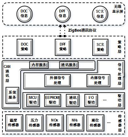
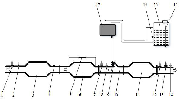
[0061] Such as figure 1 , figure 2 As shown, a real-time monitoring system for after-treatment of exhaust gas includes: sensor layer: responsible for collecting sensor signals, which are used as the basis for decision-making at the strategy layer;
[0062] Driver layer: used to ensure the stable transmission of signals at the hardware layer;
[0063] Signal processing layer: process digital signals and analog signals for use by the strategy layer;
[0064] CAN communication layer: ensure that signals are sent and received stably on the CAN bus;
[0065] Strategy layer: each decision-making module of DOC3, DPF6, and SCR11 uses a model-based method to realize the identification, feedback, and decision-making of the state of the post-processing system according to the signal of the sensor layer and the signal processed by the signal processing layer;
[0066] Wireless display screen: display real-time information, and alarm for abnormal information;
[0067] And ZigBee commu...
Embodiment 2
[0080] Such as Figure 4 As shown, in this embodiment, only DPF6-related faults are diagnosed, based on the carbon load calculation model, the loading process of DPF6 is discretized and summed, and the as a unit of time, The operating condition of the internal engine is regarded as unchanged, and the operating condition, fuel consumption, and exhaust flow of the engine are read at time T, and determined according to the emission universal characteristic curve. The original displacement of the engine particle within the time, according to the temperature difference between the first temperature sensor 2 and the second temperature sensor 4, the temperature difference between the third temperature sensor 8 and the fifth temperature sensor 18 and the basic parameters of the carrier, determine O 2 , NO 2 For the oxidation amount of particulate matter, find The amount of change in the carbon load over time, and finally the carbon load of the DPF is obtained by integrating the...
Embodiment 3
[0092] Such as Figure 5 As shown, in this embodiment, only the faults related to the urea tank 15 are diagnosed, and the PID-based closed-loop control strategy, the control principle is as shown in formula (2):
[0093] (2)
[0094] In the formula, is the proportional coefficient, is the integral coefficient, is the differential coefficient.
[0095] When the absolute value of the difference between the measured value of the third temperature sensor 8 and the measured value of the fifth temperature sensor 18 is greater than the threshold value of the temperature difference between the front and rear of the SCR11 catalytic converter, and the absolute value of the estimated residual error of the upstream temperature of the SCR11 catalytic converter is greater than the upstream temperature of the SCR11 catalytic converter When the residual threshold value is estimated, it is diagnosed that the third temperature sensor 8 upstream of the SCR11 catalytic converter is faul...
PUM
 Abstract
Description
Claims
Application Information