Lighting lamp tube manufacturing equipment

A technology for manufacturing equipment and lighting lamps, which is applied in the manufacture of tubes/lamp screens, discharge tubes/lamps, cold cathodes, etc. The effect of improving the fineness and quality of coating, avoiding uneven coating and prolonging the service life

Inactive Publication Date: 2022-01-18
江西省博林照明科技有限公司
View PDF1 Cites 0 Cited by
  • Summary
  • Abstract
  • Description
  • Claims
  • Application Information

AI Technical Summary

Problems solved by technology

[0005] 1. When the paint is just painted on the inner wall of the glass lamp tube, it still has a certain fluidity, and will gather and flow along the inner wall to the bottom due to uneven spraying, forming a thicker coating layer at the bottom of the lamp tube, resulting in When the lamp is illuminated

Method used


Image

  • Lighting lamp tube manufacturing equipment
  • Lighting lamp tube manufacturing equipment
  • Lighting lamp tube manufacturing equipment

Examples


Example Embodiment

[0034] The technical solutions in the embodiments of the present invention will be clearly and completely described below with reference to the accompanying drawings in the embodiments of the present invention. Obviously, the described embodiments are only a part of the embodiments of the present invention, but not all of the embodiments. Based on the embodiments of the present invention, all other embodiments obtained by those of ordinary skill in the art without creative efforts shall fall within the protection scope of the present invention.

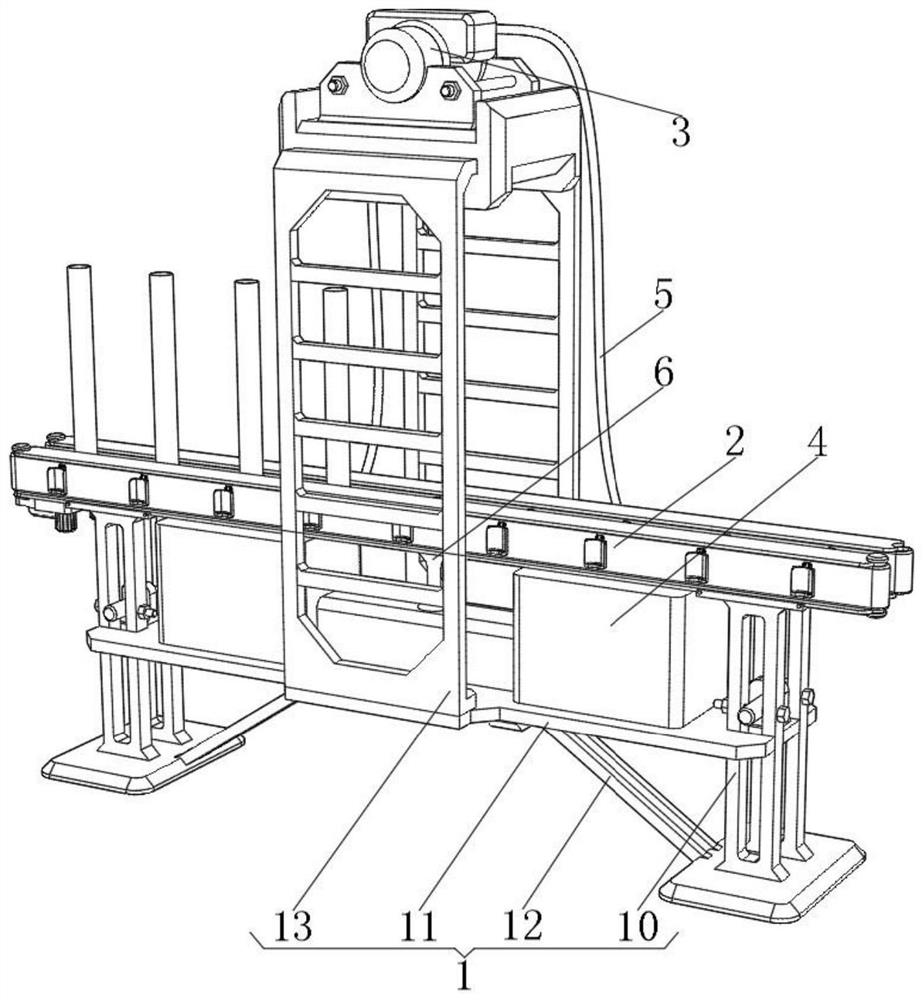
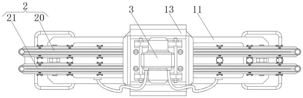
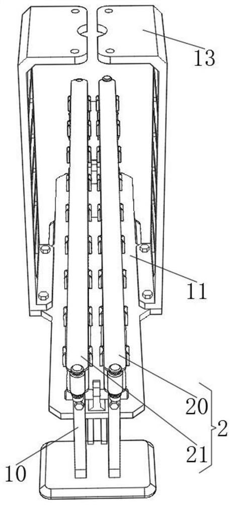
[0035] see figure 1 - Figure 8, the present invention provides the following technical solutions: a lighting tube manufacturing equipment, including a mounting frame 1, a lamp tube conveyor 2, a lamp tube coating mechanism 3 and a conduit 5, the mounting frame 1 includes two support seats 10, two support seats A splint 11 is fixedly installed between 10, the tops of the two support bases 10 are fixedly installed with the bottom of t...


PUM


Abstract

The invention belongs to the technical field of lighting lamps, and particularly relates to lighting lamp tube manufacturing equipment which comprises a mounting frame, a lamp tube conveyor, a lamp tube coating mechanism and a guide pipe, the mounting frame comprises two supporting seats, and a clamping plate is fixedly mounted between the two supporting seats; the length of a flexible telescopic tube is controlled by filling or sucking paint into or out of the telescopic tube through a pneumatic telescopic coating piece and a whipping and beating dual-purpose air pump, the paint carried at the bottom of the telescopic tube is brushed on the inner wall of a glass lamp tube for coating in the telescopic process of the telescopic tube, the problem that the glass lamp tube is scratched or impacted by a coating tool is avoided, by matching with a leak hole, redundant paint in the telescopic tube and at the bottom of the glass lamp tube is recycled, meanwhile, a conical turbine part rotating due to paint impact drives a paint brush to continuously rotate on the inner side of the glass lamp tube through a brush head clamping sleeve, and the paint brush continuously rotating and moving downwards can evenly coat the inner wall of the glass lamp tube with the paint poured into the top. The problem of non-uniform coating is avoided.

Description

technical field [0001] The invention belongs to the technical field of lighting fixtures, and in particular relates to a lighting lamp tube manufacturing equipment. Background technique [0002] The inner wall of the lighting tube will be evenly coated with a layer of phosphor powder during the manufacturing process. When ultraviolet light shines on the phosphor powder, the energy will be absorbed by the phosphor powder atoms and will transition from a low energy level to a high energy level. The atoms at the high energy level are unstable. , and will spontaneously transition from high energy level to low energy level, and emit photons of different frequencies, thus emitting visible light with a wavelength between 400nm and 770nm, in order to realize the function of lighting, coating the inner wall of the lighting tube with phosphor will use A coating device. [0003] In the prior art, such as the Chinese Patent No.: CN 208466363 U's "a photocatalyst lamp tube production co...

Claims


Application Information

Patent Timeline
IPC IPC(8): H01J9/18H01J9/22H01J9/38H01J9/48
CPCH01J9/18H01J9/22H01J9/38H01J9/48
Inventor 周恒平
Owner 江西省博林照明科技有限公司
Why Eureka
Try Eureka