
Marine fuel cell cathode inflow gas salt content detection and desalting system and method and marine fuel cell system

A fuel cell cathode, fuel cell technology, applied in fuel cells, fuel cell additives, batteries, etc., can solve the problems of unsuitable energy efficiency fuel cell systems, reduced fuel cell conductivity, no automatic control function, etc., to avoid The effect of fast wear, high degree of automation and convenient operation

Pending Publication Date: 2022-01-25
氢普(德州)新能源科技有限公司
View PDF16 Cites 0 Cited by
  • Summary
  • Abstract
  • Description
  • Claims
  • Application Information

AI Technical Summary

Problems solved by technology

CN212648289U "A Fuel Cell Cooling Water Purification System and Fuel Cell System" discloses only the passive purification function of the cooling liquid, and cannot avoid the problem of accelerating the loss of the proton membrane
The method of CN213340446U "a kind of system that reduces electric conductivity of fuel cell" also only relates to coolant and is only applicable to fuel cell test equipment
CN206008332U "A kind of air desalination system" is only used in the situation of fan blowing air, and is not suitable for the pressure intake situation of the fuel cell used in conjunction with the air compressor, and it has no automatic control function, and is not suitable for the fuel cell system sensitive to energy efficiency. Be applicable

Method used


Image

  • Marine fuel cell cathode inflow gas salt content detection and desalting system and method and marine fuel cell system
  • Marine fuel cell cathode inflow gas salt content detection and desalting system and method and marine fuel cell system
  • Marine fuel cell cathode inflow gas salt content detection and desalting system and method and marine fuel cell system

Examples


Embodiment 1

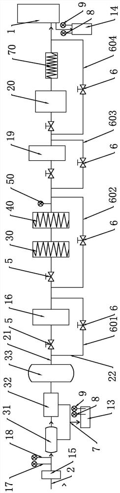
[0061] Such as figure 1 As shown, the marine fuel cell cathode air intake salt content detection and desalination system includes a fuel cell 1, and an air intake module 3 and a desalination module 4 connected through a gas pipeline 2 are arranged at the cathode end of the fuel cell; The air intake module 3 includes an air compressor 31, an intercooler 32, and an air storage tank 33 connected in sequence; the desalination module 4 includes a front-stage salinity detection structure, a desalination structure and a rear-end salinity detection structure. The salinity detection structure is used to detect the salinity value in the drainage of the air compressor 31 and the intercooler 32; the rear-end salinity detection structure is used to detect the salinity value in the cathode product water of the fuel cell 1;

[0062] A main pipeline 21 and a bypass pipeline 22 are arranged on the gas pipeline 2 connected to the exhaust port of the gas storage tank 33, and the desalination str...

Embodiment 2

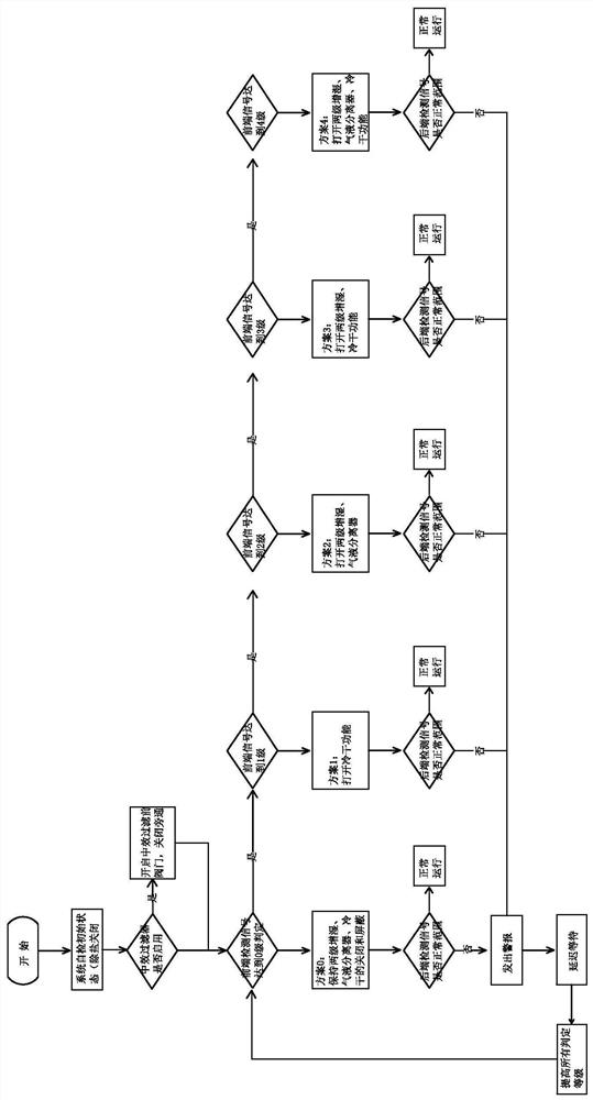
[0082] Such as figure 2 As shown, the method for detecting and desalting the fuel cell cathode intake air salt content by using the marine fuel cell cathode intake salt content detection and desalination system as in Example 1 adopts the following steps:

[0083] (1) Preset the salinity value of the front stage and the salinity value of the rear end, and the controller judges whether to desalinate the initial salt content of the cathode intake air processed by the air compressor intake module according to the salinity value of the front stage, And according to the salinity value of the previous stage, determine the level of cathode air intake that needs desalination treatment, and select the corresponding desalination treatment plan;

[0084] The steps to determine whether to desalinate the initial salt content of the initial salinity value are:

[0085] a According to different salinity values, the previous salinity value is divided into 0 grade, 1 grade, 2 grade, 3 grade a...

Embodiment 3

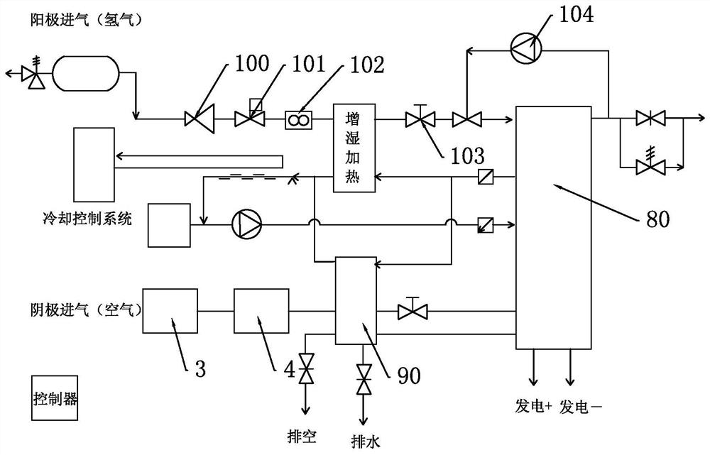
[0104] Such as image 3 As shown, it is a marine fuel cell system diagram obtained by adopting the marine fuel cell cathode air intake salt content detection and desalination system of Example 1, wherein the anode air intake system controls and delivers hydrogen, which is passed into the anode side of the fuel cell, and the gas Air intake pressure and flow control is realized through safety valve, check valve, pressure limiting valve 100, pressure regulating valve 101, mass flow meter 102, back pressure valve 103, etc.; temperature and humidity control of intake air is realized through humidification and heating; Hydrogen reflux and pulse exhaust are realized through the hydrogen circulation pump 104 and solenoid valves. The cathode air intake system controls and delivers air, and uses the oxygen in the air as a reducing agent to participate in the fuel discharge reaction. The coolant is controlled by the cooling control system to realize the temperature control of the fuel c...


PUM


Abstract

The invention belongs to the technical field of fuel cell generator systems and relates to a marine fuel cell cathode inflow gas salt content detection and desalting system and method and a marine fuel cell system. The marine fuel cell cathode inflow gas salt content detection and desalting system comprises a fuel cell, a controller, a gas compression air inflow module and a desalting module, wherein the air compression gas inflow module and the desalting module are connected through a gas conveying pipeline; the air compression gas inflow module comprises an air compressor, an intercooler and a gas storage tank; the desalting module comprises a front-stage salinity detection structure, a desalting structure and a rear-end salinity detection structure, a main pipeline and a bypass pipeline are arranged on the gas conveying pipeline, and the desalting structure is arranged on the main pipeline; and a valve is arranged at the gas inflow end of the desalting structure, and a bypass valve is arranged on the bypass pipeline. The marine fuel cell cathode inflow gas salt content detection and desalting system can realize real-time detection of salt content of cathode inflow gas used by a fuel cell, automatically desalt the cathode inflow gas, avoid rapid loss of parts such as an internal proton exchange membrane and the like, prolong the service life of the fuel cell and better adapt to marine working conditions.

Description

technical field [0001] The invention relates to the technical field of fuel cell generator systems, in particular to a system and method for detecting and desalting the salt content in the intake air of a marine fuel cell cathode and a marine fuel cell system. Background technique [0002] Fuel cells have the advantages of zero emissions, high efficiency, diversified fuel sources, and renewable energy. The development of fuel cell technology has become a breakthrough in global energy transformation. Proton exchange membrane fuel cells typically use hydrogen as fuel, fed from the anode side of the cell, and oxygen from the air as the oxidant, fed from the cathode side. The fuel hydrogen is transported to the cathode on the other side of the proton exchange membrane after the anode removes electrons through electrocatalysis, and electrochemically reacts with the catalyzed oxygen to directly generate electricity. The waste is only water, which is an ideal form of clean power ge...

Claims


Application Information

Patent Timeline
Patent Type & Authority Applications(China)
IPC IPC(8): H01M8/04082H01M8/04119
CPCH01M8/04216H01M8/04119H01M2220/20Y02E60/10Y02E60/50
Inventor 吕鹏黄伟
Owner 氢普(德州)新能源科技有限公司
Learn More