Rapid steam turbine coupling bolt disassembling tool and using method

A steam turbine and wheel bolt technology, which is applied in metal processing, manufacturing tools, metal processing equipment, etc., can solve the problems of small gap spacing, high technical requirements of construction personnel, and many precision thermal control measuring probes, etc. The effect of shortening dismantling steps and improving dismantling efficiency

Pending Publication Date: 2022-01-28
广东华电韶关热电有限公司
View PDF0 Cites 0 Cited by
  • Summary
  • Abstract
  • Description
  • Claims
  • Application Information

AI Technical Summary

Problems solved by technology

[0004] However, the sledgehammer vibration method has the following problems: 1. There are many precision thermal control measurement probes installed between the high-medium pressure coupling bearing boxes of the unit. It is necessary to remove all thermal control probes and brackets before dismantling the high-middle wheel. It takes about 1 day to complete the pre-repair data check and dismantling of all probes for the thermal control precision probe. The overhaul period brings certain obstacles; 2. The space between the high-medium pressure pairing wheel equipment is relatively small. When dismantling the pairing wheel bolts by vibrating method, it not only requires high skill of the construction personnel, but also needs to use rubber pads or cardboard in advance The high-medium pressure part of the steam turbine journal, thrust disc, expansion disc, axial displacement device, etc. are fully wrapped and protected to avoid damage to the precise parts of the rotor caused by the sledgehammer during construction; 3. Necessary when disassembling the pin bolts Copper rods are used as power transmission transition tools. Because the pin bolts are arranged along the outer circumference of the coupling, the copper rods have no reliable and stable support points for fixing. During the whole process of disassembling the pin bolts, manual hands are required to hold the copper rods firmly. tapping job
Make maintenance work time-consuming and laborious

Method used


Image

  • Rapid steam turbine coupling bolt disassembling tool and using method

Examples


Embodiment Construction

[0026] The present invention will be described in detail below in conjunction with the accompanying drawings and embodiments.

[0027] It is worth noting that the orientation words such as "up" and "down" involved in this article are all determined relative to the perspective of the drawings, and are only for the convenience of description, and cannot be understood as limitations on the technical solution.

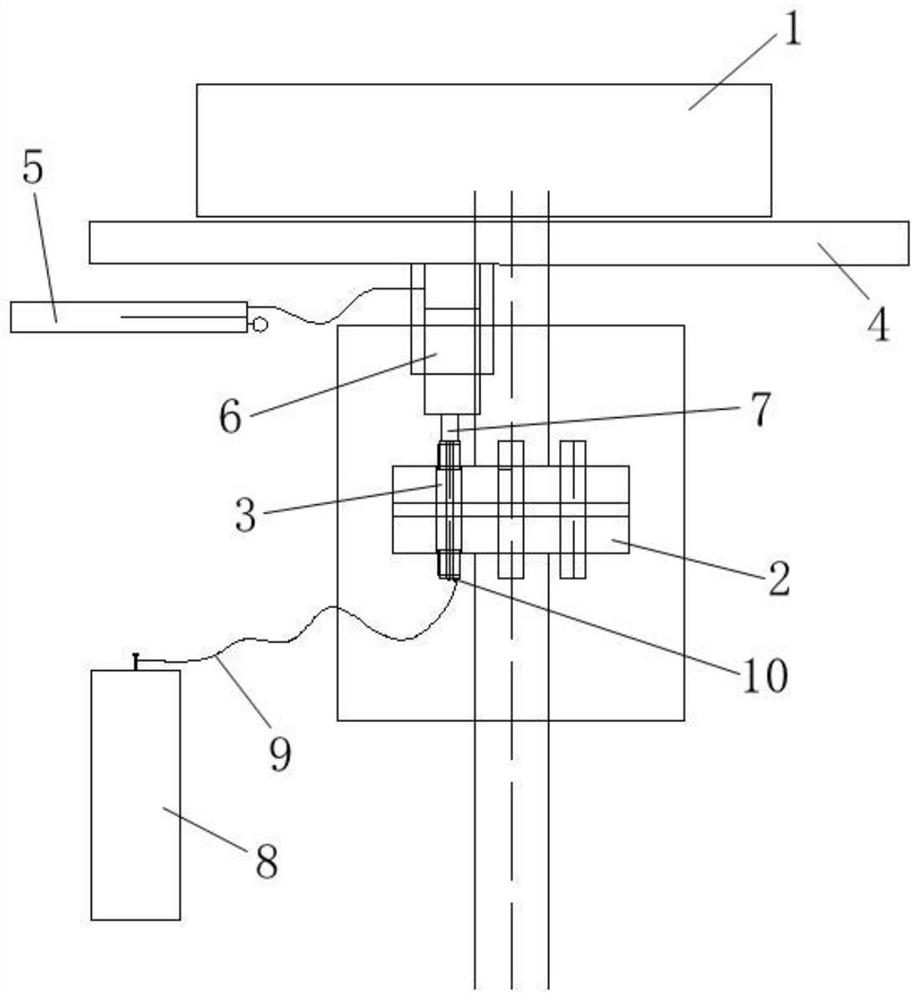
[0028] Such as figure 1 As shown, the present invention provides a fast steam turbine counter-wheel bolt dismantling tool, including a ejection mechanism and a cooling mechanism. The ejection mechanism is arranged between the counter-wheel 2 and the steam turbine 1, and the ejection mechanism and the counter-wheel One end of the pin bolt 3 of 2 is in contact; the cooling device is in contact with the other end of the pin bolt 3 .

[0029] The steam turbine 1 has been in a high-speed rotation state of 3000r / min for a long time during operation. In order to transmit the rot...


PUM


Abstract

The invention relates to a rapid steam turbine coupling bolt disassembling tool which comprises an ejection mechanism and a cooling mechanism, the ejection mechanism is arranged between a coupling and a steam turbine, and the ejection mechanism is in contact with one end of a pin shaft bolt of the coupling; and the cooling device is in contact with the other end of the pin shaft bolt. The invention further relates to a using method of the rapid steam turbine coupling bolt disassembling tool, ultralow-temperature liquid nitrogen is rapidly injected into the pin shaft bolt through the adapter, heat is rapidly absorbed through gasification of the liquid nitrogen, the pin shaft bolt is rapidly cooled to subzero temperature, the volume of the pin shaft bolt is shrunk at the low temperature, the fit clearance between the pin shaft bolt and the through hole of the coupling is increased, and the ejector rod of the efficient long-stroke oil jack is driven by the manual hydraulic pump to extend out to eject out the pin shaft bolt. The unit maintenance quality is effectively improved, the labor intensity of maintenance workers is greatly relieved, the unit maintenance period is guaranteed, and the operation safety of constructors is guaranteed.

Description

technical field [0001] The invention relates to a dismantling tool, more specifically, it relates to a fast steam turbine anti-wheel bolt dismantling tool and its use method. Background technique [0002] The main function of the steam turbine coupling is to connect the steam turbine and the generator rotor through the rigid connection of the coupling, and transmit the rotational force of the steam turbine rotor to the generator to realize energy conversion. At the same time, the axial thrust between the rotors is transmitted through the rigid coupling. To the thrust pad, it is used to ensure the axial safety clearance during the operation of the steam turbine generator set. [0003] Rigid couplings for steam turbines have the advantages of large torque transmission, large shearing force and simple structure, but the disadvantages are small center deviation, strict maintenance process requirements, high assembly accuracy, heavy connection and adjustment procedures, dismantli...

Claims


Application Information

Patent Timeline
Patent Type & Authority Applications(China)
IPC IPC(8): B23P19/06B23P19/027
CPCB23P19/06B23P19/027
Inventor 刘镇荣吴振凌吕刚惠阿兵涂元刘凡赵新宝袁勇
Owner 广东华电韶关热电有限公司
Why Eureka
Try Eureka