
Milling cutter cleaning device

A cleaning device and milling cutter technology, applied in electrode cleaning, maintenance and safety accessories, external electrostatic separators, etc., can solve the problem of waste chip adhesion, etc., to increase the adhesion area, strengthen the absorption effect, and increase the number of effects.

Active Publication Date: 2022-01-28
江西华派光电科技有限公司
View PDF10 Cites 0 Cited by
  • Summary
  • Abstract
  • Description
  • Claims
  • Application Information

AI Technical Summary

Problems solved by technology

[0005] In order to solve the problem of scrap attachment during milling cutter processing, and to prevent the scraps from floating in the production workshop and affecting the safety of workers, the present invention can protect the milling cutter For cleaning, a milling cutter cleaning device is provided

Method used


Image

  • Milling cutter cleaning device
  • Milling cutter cleaning device
  • Milling cutter cleaning device

Examples


Embodiment Construction

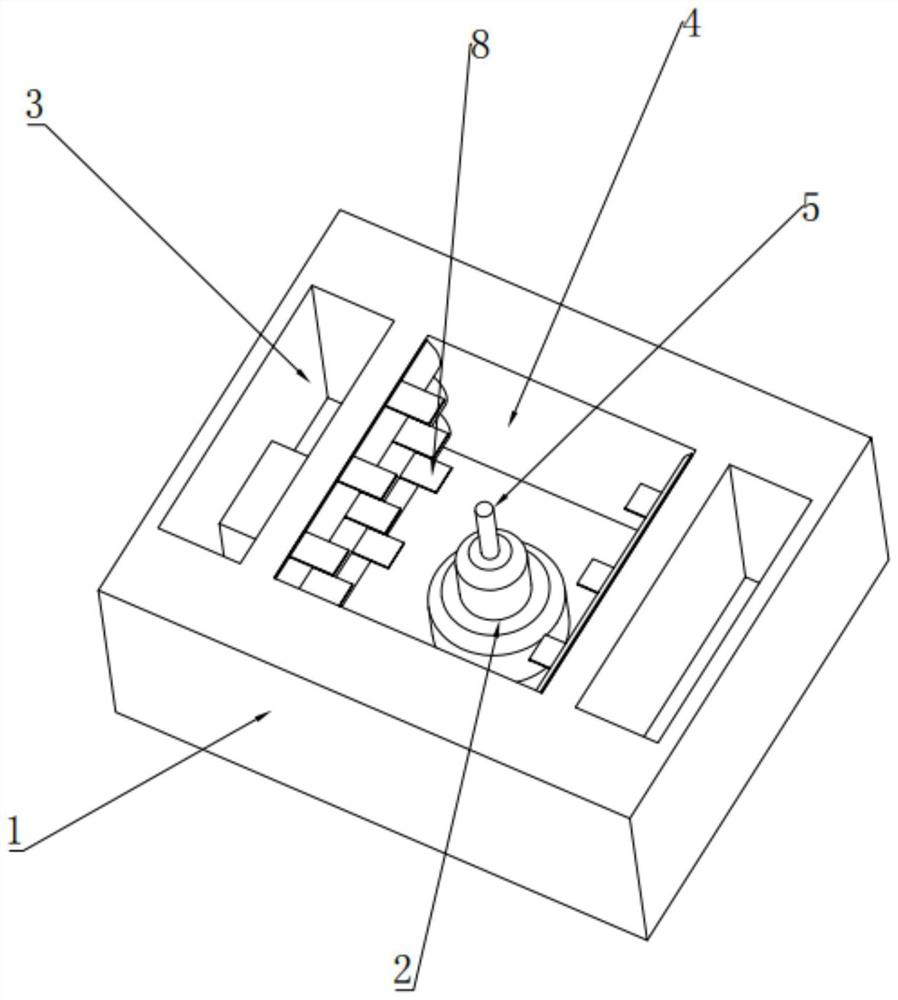
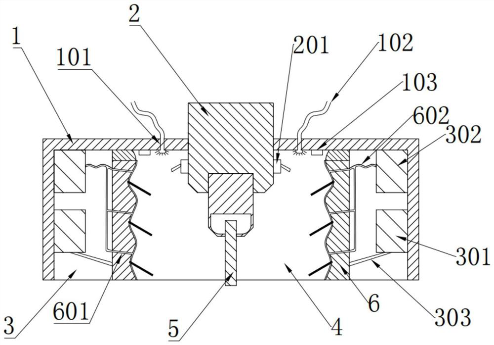
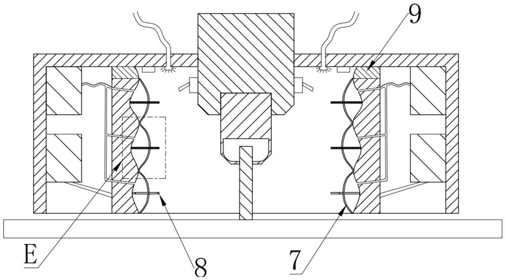
[0020] A milling cutter cleaning device, which includes a housing 1, which can be fixed on a milling machine spindle mechanism 2, the housing 1 is provided with a working chamber 3 and a cleaning chamber 4, and the working chamber 3 is located in the On both sides of the housing 1, the cleaning cavity 4 has a spindle mechanism 2 of the milling machine, and the milling cutter 5 is fixed to the spindle mechanism 2 for work. The spindle mechanism 2 is provided with a laser transmitter 201. The cleaning cavity 4 An electrostatic wall 6 is arranged between the working chamber 3, and an electrostatic generator 301 and an air pump 302 are arranged in the working chamber 3. The electrostatic generator 301 is connected to the electrostatic wall 6 through an electrostatic rod 303, and the electrostatic wall 6 There is a ventilation hole 601 on the upper part, and the air pump 302 communicates with the ventilation hole 601 through the air pipe 602. The upper end of the housing 1 is evenly...


PUM


Abstract

A milling cutter cleaning device is characterized in that the milling cutter cleaning device comprises a shell, the shell can be fixed to a main shaft mechanism of a milling machine, the shell is provided with working cavities and a cleaning cavity, the working cavities are located on the two sides of the shell, the main shaft mechanism of the milling machine is arranged in the cleaning cavity, and meanwhile a milling cutter is fixed to the main shaft mechanism to work. The invention provides a milling cutter cleaning device in order to solve the problem of attachment of sweeps in the milling cutter machining process, prevent the sweeps from drifting away in a production workshop to affect the safety of workers and clean a milling cutter at the same time.

Description

technical field [0001] The invention belongs to the field of cleaning devices, in particular to a milling cutter cleaning device. Background technique [0002] Milling cutter is a rotary cutter with one or more teeth for milling. Each cutter tooth cuts off the allowance of the workpiece intermittently during operation. The milling cutter is mainly used for machining planes, steps and grooves on a milling machine. Grooving, forming surfaces and parting workpieces, etc., in order to ensure that a sufficiently high average chip thickness is used, it is necessary to correctly determine the number of milling cutter teeth suitable for the operation. [0003] Among them, when the milling cutter is used to process some glass products or plastic materials, a large amount of fine waste will be generated during the processing. This waste will be attached to the milling cutter during the processing. This leads to precision errors in the processing of high-precision glass and plastic pr...

Claims


Application Information

Patent Timeline
Patent Type & Authority Applications(China)
IPC IPC(8): B23Q11/00B03C3/04B03C3/47B03C3/68B03C3/78
CPCB23Q11/0046B03C3/04B03C3/47B03C3/68B03C3/78
Inventor 李健
Owner 江西华派光电科技有限公司
Learn More