Method and device for deacidifying hot flue gas

A technology of hot flue gas and deacidification, applied in the field of heat treatment, can solve problems such as treating the symptoms but not the root cause, increasing equipment costs, etc., to achieve the effect of improving efficiency and reducing the probability of corrosion and blockage

Pending Publication Date: 2022-02-01
ZHE JIANG ECO ENVIRONMENTAL TECH CO LTD
View PDF24 Cites 1 Cited by
  • Summary
  • Abstract
  • Description
  • Claims
  • Application Information

AI Technical Summary

Problems solved by technology

However, the above-mentioned device is a temporary solution, not a permanent cure, and frequent replacement of the spray device will cause an increase in equipment costs.

Method used


Image

  • Method and device for deacidifying hot flue gas
  • Method and device for deacidifying hot flue gas
  • Method and device for deacidifying hot flue gas

Examples


Embodiment 1

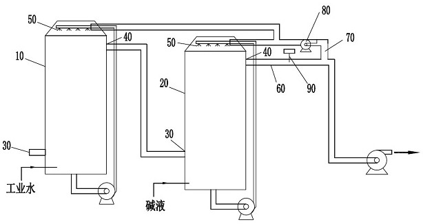
[0024] Such as figure 1 As shown, the device for deacidification of hot flue gas according to the present invention has a main body of a precooling tower 10 and a deacidification tower 20, the precooling tower 10 is arranged before the deacidification tower 20, and the precooling tower 10 Industrial water is used for spray cooling, and the deacidification tower 20 is deacidified and cooled with lye.

[0025] The sides of the precooling tower 10 and the deacidification tower 20 are both provided with a flue gas inlet 30 and a flue gas outlet 40 . The acidic hot flue gas enters the precooling tower 10 at first. A spray head 50 is arranged on the top of the pre-cooling tower 10 . The hot flue gas is in countercurrent contact with the fine liquid particles coming out of the shower head 50 to realize the cooling of the hot flue gas, and the easily soluble gas in the hot flue gas is also removed at the same time. The innovation of the present invention is: the deacidified flue ga...

Embodiment 2

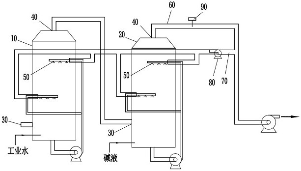
[0030] Such as figure 2 Shown, the difference between this embodiment and embodiment 1 is:

[0031] 1. The spray heads 50 in the pre-cooling tower 10 and the deacidification tower 20 are no longer a single layer, but are arranged in two layers, including an upper layer spray head and a lower layer spray head, and the lower layer spray head is located at the flue gas inlet 30 on one side. The staggered setting of the upper spray head and the lower spray head makes the hot flue gas move in an S shape in the precooling tower 10 and the deacidification tower 20, which is conducive to increasing the lateral flow of the hot flue gas and making the cooling and deacidification of the hot flue gas more efficient. full.

[0032] 2. The flue gas outlet 40 of the precooling tower 10 and the deacidification tower 20 is no longer arranged on the side of the precooling tower 10 and the deacidification tower 20, but is arranged on the top of the precooling tower 10 and the deacidification ...


PUM


Abstract

The invention relates to the technical field of heat treatment, in particular to a method and a device for deacidifying hot flue gas. The method for deacidifying the hot flue gas sequentially comprises a pre-cooling step and a deacidifying step. In the pre-cooling step, a spray header is used for spraying cooling water to the hot flue gas. In the deacidification step, a spray header is used for spraying alkali liquor on the hot flue gas to obtain deacidified flue gas, a part of the deacidified flue gas is guided back to the pre-cooling step and / or the deacidification step, and the returned deacidified flue gas is used for performing gas washing on the spray header. When the method and the device provided by the invention are used for carrying out deacidification treatment on the acidic hot flue gas, the cooling and deacidification efficiency can be improved, and meanwhile, the probability that the spray header is corroded and blocked can be reduced.

Description

technical field [0001] The invention relates to the technical field of heat treatment, in particular to a method and device for deacidifying hot flue gas. Background technique [0002] At present, among many hazardous waste treatment technologies, pyrolysis technology has the advantages of the most complete harmlessness, the most significant volume reduction, and the highest degree of resource utilization. During the pyrolysis process, some pollutants are inevitably produced, mainly including acid gases (HCl, SO 2 , NOx, etc.), dust particles, organic toxic pollutants, etc. HCI gas is generated from the pyrolysis of components containing CI elements in waste, including organic chlorides (represented by polyvinyl chloride) and inorganic chlorides (represented by KCI). For example, the main component of medical waste is PVC-like chlorinated organic matter. Therefore, during the pyrolysis process of medical waste, more acid gas will be generated. The acid gas will corrode met...

Claims


Application Information

Patent Timeline
Patent Type & Authority Applications(China)
IPC IPC(8): B01D53/78B01D53/40B01D53/18B01D47/06F28C1/06
CPCB01D53/78B01D53/40B01D53/18B01D47/06F28C1/06B01D2258/0283B01D2251/304B01D2251/604B01D2251/606
Inventor 于立松田汪洋车磊吴玉祥李森
Owner ZHE JIANG ECO ENVIRONMENTAL TECH CO LTD
Why Eureka
Try Eureka