Spray pipe and aircraft afterbody slit exhaust cooling device

A cooling device and slit technology, used in jet propulsion devices, exhaust ports of power plants, machines/engines, etc., can solve the problems of reducing the strength of the heat shield, damage to the heat shield, poor cooling effect, etc. Processing difficulty and processing cost, improving overall strength, and the effect of large cooling range

Pending Publication Date: 2022-02-08
AECC SHENYANG ENGINE RES INST
View PDF10 Cites 2 Cited by
  • Summary
  • Abstract
  • Description
  • Claims
  • Application Information

AI Technical Summary

Problems solved by technology

[0005] 1) A large number of holes in the heat shield on the side wall of the engine nozzle will greatly increase the radar reflection intensity of the nozzle and reduce the stealth effect of the binary nozzle. At the same time, a large number of holes on the surface of the heat shield will reduce the strength of the heat shield, and The aerodynamic stress generated by the pressure difference inside and outside the heat shield and the thermal stress generated by the high-temperature jet will concentrate on the opening position, which will easily cause damage to the heat shield. In order to meet the strength requirements of the heat shield, the thickness of the heat shield must be increased. Increase nozzle weight;
[0006] 2) A large number of holes are opened on the heat shield, and the process is complicated, which will increase the processing difficulty and cost, and the performance and machinability of the material are high, and the range of available materials is small;
[0007] 3) In film cooling, the incident angle of cold air cannot be parallel to the wall surface, and the mixing effect with high-temperature jet flow is strong, and the wall surface is not easy to be completely covered by cold air, and the cooling effect is poor

Method used


Image

  • Spray pipe and aircraft afterbody slit exhaust cooling device
  • Spray pipe and aircraft afterbody slit exhaust cooling device
  • Spray pipe and aircraft afterbody slit exhaust cooling device

Examples


Embodiment Construction

[0026] In order to make the objectives, technical solutions and advantages of the implementation of the application clearer, the technical solutions in the implementation modes of the application will be described in more detail below with reference to the drawings in the implementation modes of the application. In the drawings, the same or similar reference numerals denote the same or similar elements or elements having the same or similar functions throughout. The described embodiments are some, but not all, embodiments of the present application. The embodiments described below by referring to the figures are exemplary and are intended to explain the present application, and should not be construed as limiting the present application. Based on the implementation manners in this application, all other implementation manners obtained by persons of ordinary skill in the art without creative efforts fall within the scope of protection of this application. Embodiments of the pr...


PUM


Abstract

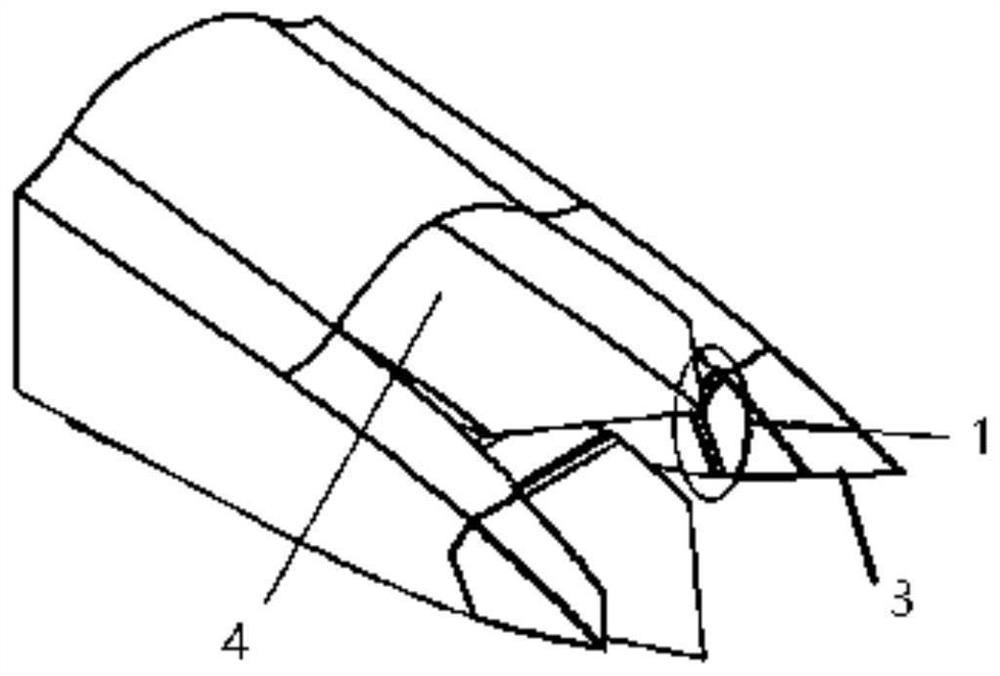
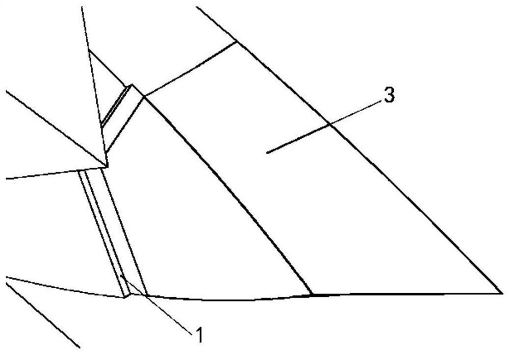
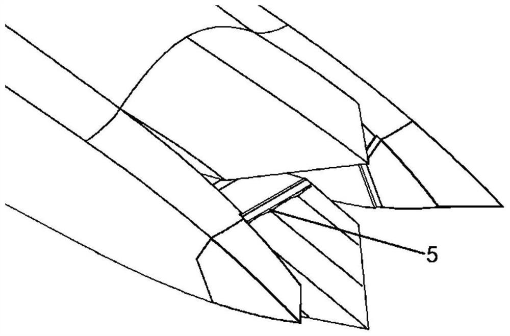
The invention belongs to the technical field of engine design, and particularly relates to a spray pipe and an aircraft afterbody slit exhaust cooling device. The device comprises a gas collecting cavity communicated with an engine outer culvert, the gas collecting cavity is located between the side wall of a spray pipe and the inner wall face and the outer wall face of a throat adjusting piece, the gas collecting cavity is provided with a side wall exhaust slit (1) at the rear end of the side wall of the spray pipe, the side wall exhaust slit (1) is formed in the front side of an aircraft afterbody or a tail cone (3), and exhaust of the side wall exhaust slit (1) is roughly parallel to the jet flow direction of the spray pipe; the air collecting cavity is provided with an expansion section exhaust slit (5) on the inner wall surface of the expansion section of the throat adjusting sheet of the spray pipe, and the exhaust direction of the expansion section exhaust slit (5) is approximately parallel to the airflow flowing direction of the near wall surface of the expansion section adjusting sheet of the spray pipe. The overall strength of the cooling mechanism is improved, the machining difficulty and the machining cost are reduced, the cooling range of the spray pipe and the aircraft afterbody is larger, the cooling effect is better, and meanwhile the backward radar stealth and infrared stealth effects of an aircraft can be better improved.

Description

technical field [0001] The application belongs to the technical field of engine design, and in particular relates to a nozzle and an aircraft rear body slit exhaust cooling device. Background technique [0002] After adopting rectangular nozzles such as binary thrust vectoring nozzles and unilateral expansion nozzles, the aircraft generally adopts a pointed tail vertebra structure, so that the aircraft as a whole meets the requirements of supersonic speed area ratio and reduces the pressure difference resistance of the rear body. It generally accommodates equipment such as drogue parachute and backward detection. Because important equipment will be accommodated in the tail cone, and a large number of composite materials are used on the surface and the stealth coating is sprayed. The temperature resistance of composite materials and stealth coatings is poor, so higher requirements are put forward for the thermal protection ability of the rear body of the aircraft. [0003] T...

Claims


Application Information

Patent Timeline
Patent Type & Authority Applications(China)
IPC IPC(8): F02K1/82B64D33/04
CPCF02K1/822F02K1/825B64D33/04B64D2033/045
Inventor 杨瀚超田方超任智博白伟
Owner AECC SHENYANG ENGINE RES INST
Why Eureka
Try Eureka