Design method and system for oil smoke exhaust duct

A design method and oil fume exhaust technology, applied in special data processing applications, instruments, electrical digital data processing, etc., can solve the problems of the oil fume exhaust system and the unsuitable method of the flue size, so as to reduce the area occupied by the well and ensure the emission effect of effect

Pending Publication Date: 2022-02-11
CHINA CONSTR STEEL STRUCTURE CORP LTD
View PDF0 Cites 0 Cited by
  • Summary
  • Abstract
  • Description
  • Claims
  • Application Information

AI Technical Summary

Problems solved by technology

[0003] Therefore, the technical problem to be solved by the present invention is to overcome the defect that the method for determining the size of the oil fume exhaust system and the flue in the prior art is not suitable for the current architectural design, thereby providing a method and system for designing the oil exhaust flue

Method used


Image

  • Design method and system for oil smoke exhaust duct
  • Design method and system for oil smoke exhaust duct
  • Design method and system for oil smoke exhaust duct

Examples


Embodiment 1

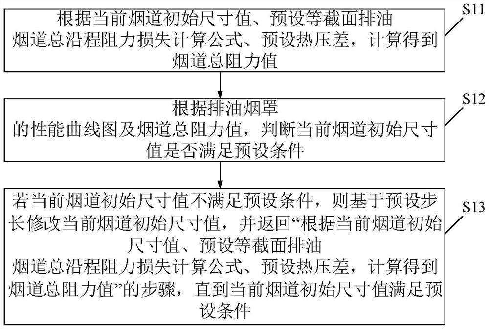
[0033] Embodiments of the present invention provide a method for designing an oil exhaust flue, such as figure 1 As shown, steps S11 to S13 are included, specifically as follows:

[0034] Step S11: Calculate the total resistance value of the flue according to the current initial size value of the flue, the preset formula for calculating the total resistance loss along the process of the equal-section oil discharge flue, and the preset thermal pressure difference.

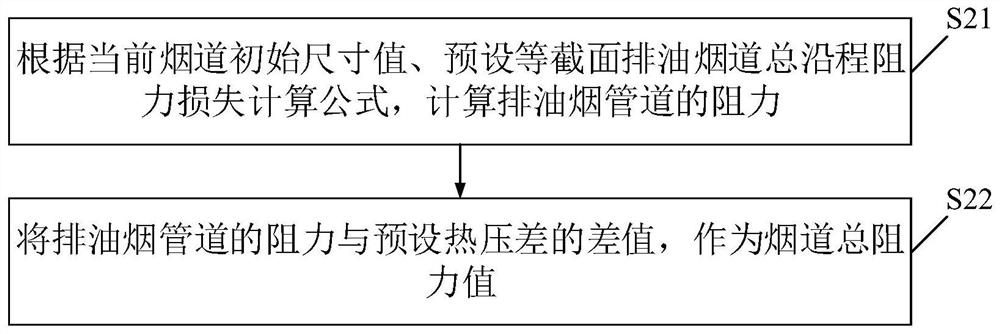
[0035] Specifically, such as figure 2 As shown, obtaining the total resistance value of the flue is performed by specific steps S21 to S22, as follows:

[0036] Step S21: Calculate the resistance of the oil fume exhaust duct according to the current initial size value of the flue and the preset formula for calculating the total resistance loss of the oil exhaust flue with equal cross-section.

[0037] Step S22: The difference between the resistance of the oil fume exhaust pipe and the preset thermal pressure diff...

Embodiment 2

[0101] An embodiment of the present invention provides an oil exhaust flue design system, such as Figure 7 shown, including:

[0102] Calculation module 1 of the total resistance value of the flue, which is used to calculate the total resistance value of the flue according to the current initial size value of the flue, the preset calculation formula of the total resistance loss along the oil discharge flue with equal cross-section, and the preset thermal pressure difference; this module Execute the method described in step S11 in Embodiment 1, which will not be repeated here.

[0103] Judgment module 2, for judging whether the initial size value of the current flue meets the preset condition according to the performance curve diagram of the oil exhaust hood and the total resistance value of the flue; this module executes the method described in step S12 in Embodiment 1, and This will not be repeated here.

[0104] The adjustment module 3 is used to modify the initial size v...

Embodiment 3

[0106] An embodiment of the present invention provides a computer device, such as Figure 8 As shown, it includes: at least one processor 401 , such as a CPU (Central Processing Unit, central processing unit), at least one communication interface 403 , memory 404 , and at least one communication bus 402 . Wherein, the communication bus 402 is used to realize connection and communication between these components. Wherein, the communication interface 403 may include a display screen (Display) and a keyboard (Keyboard), and the optional communication interface 403 may also include a standard wired interface and a wireless interface. The memory 404 may be a high-speed RAM memory (Ramdom Access Memory, volatile random access memory), or a non-volatile memory (non-volatile memory), such as at least one disk memory. Optionally, the memory 404 may also be at least one storage device located away from the aforementioned processor 401 . Wherein, the processor 401 can execute the metho...


PUM


Abstract

The invention discloses a design method and system for an oil smoke exhaust duct. The method comprises the steps of carrying out the calculation according to a current initial size value of a flue, a preset calculation formula of the total on-way resistance loss of the uniform-section oil smoke exhaust duct, and a preset hot pressure difference, and obtaining a total resistance value of the flue through calculation, judging whether the current initial size value of the flue meets a preset condition or not according to the performance curve graph of the oil smoke exhaust hood and the total resistance value of the flue, if the initial size value of the current flue does not meet the preset condition, modifying the initial size value of the current flue based on a preset step length, and returning to the step of calculating to obtain the total resistance value of the flue according to the initial size value of the current flue, the preset total on-way resistance loss calculation formula of the uniform-section oil exhaust flue and the preset hot pressure difference until theinitial size value of the current flue meets the preset condition, and thus, theinitial size of the flue meeting the condition is obtained. According to the flue size table recommended by the method and the smoke exhaust hood arrangement principle, the emission effect can be guaranteed, and the occupied area of the shaft is reduced as much as possible.

Description

technical field [0001] The invention relates to the technical field of architectural design, in particular to a design method and system for an oil discharge flue. Background technique [0002] In recent years, there have been more and more new super high-rise residential projects, and the height of towers has also continued to break through. However, the current codes, standards or atlases applicable to residential kitchen exhaust ducts, the maximum burden height or the number of floors, no longer meet the current design needs , and different projects have different oil fume exhaust systems. After the height of the tower exceeds the range that can be selected by referring to the specification or atlas, how to determine the oil fume exhaust system and the size of the flue has become a difficult point in the design of the project. Contents of the invention [0003] Therefore, the technical problem to be solved by the present invention is to overcome the defect that the meth...

Claims


Application Information

Patent Timeline
Patent Type & Authority Applications(China)
IPC IPC(8): G06F30/17G06F111/10G06F119/14
CPCG06F30/17G06F2119/14G06F2111/10
Inventor 于振峰徐坤高鹏徐聪陈志谋曾庆雄潘智坚康瑞张鑫鑫
Owner CHINA CONSTR STEEL STRUCTURE CORP LTD
Why Eureka
Try Eureka