
Optical signal processing method, photon neural network chip, and design method of chip

A neural network and optical signal technology, applied in the processing of optical signals, photonic neural network chips and their design fields, can solve the problems of photonic neural network staying, difficult to integrate, and difficult to integrate, and achieves fast computing speed, mature promotion and promotion , the effect of improving computing efficiency

Pending Publication Date: 2022-02-11
SUZHOU LANGCHAO INTELLIGENT TECH CO LTD
View PDF5 Cites 2 Cited by
  • Summary
  • Abstract
  • Description
  • Claims
  • Application Information

AI Technical Summary

Problems solved by technology

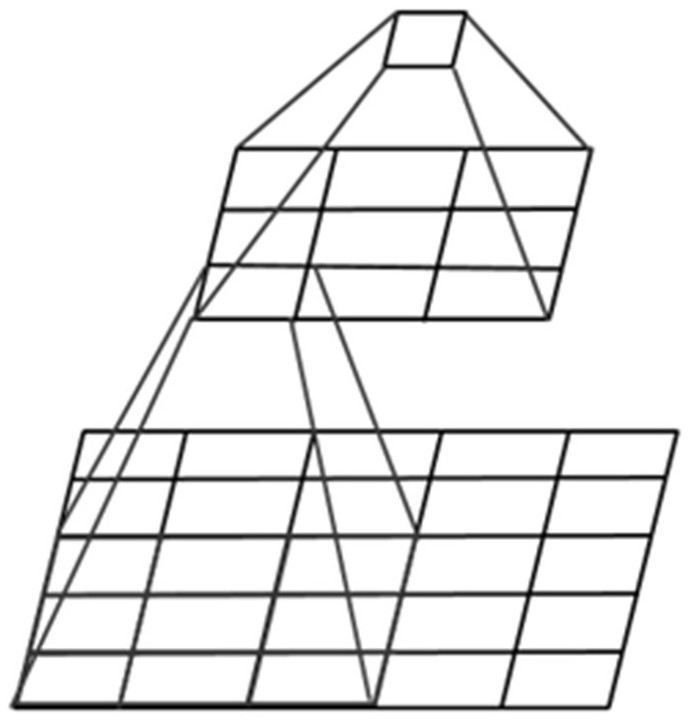
[0005] On the one hand, the convolutional layer is an important part of the neural network. The existing optical neural network is mainly realized by the Fourier 4f system or the spatial light modulator. The disadvantages of these two methods are that the device size is large, it is difficult to integrate, and It's all about the convolution operation of the whole image, and most of the implementations with integrated optical chips on the chip are just fully connected neural networks
[0006] On the other hand, due to the large number of devices required to build an optical neural network, on-chip integration is difficult, and it is difficult to reliably apply to large-scale optical networks. Therefore, most of the existing on-chip photonic neural networks stay in the research of single-layer networks.
However, since the advantages (power and speed) of analog accelerators are only useful for very large networks, the parallelism and high-speed advantages of optical chips have not yet been demonstrated on artificial intelligence neural networks.

Method used


Image

  • Optical signal processing method, photon neural network chip, and design method of chip
  • Optical signal processing method, photon neural network chip, and design method of chip
  • Optical signal processing method, photon neural network chip, and design method of chip

Examples


Embodiment Construction

[0060] In order to make the purposes, technical solutions and advantages of the embodiments of the present application clearer, the technical solutions in the embodiments of the present application will be clearly and completely described below in conjunction with the drawings in the embodiments of the present application. Obviously, the described embodiments It is a part of the embodiments of the present application, rather than all the embodiments. The schematic embodiments of the present application and their descriptions are used to explain the present application, and do not constitute an improper limitation of the present application. All other embodiments obtained by persons of ordinary skill in the art based on the embodiments in the present application without creative efforts shall fall within the protection scope of the present application.

[0061] It should be noted that in this article, relative terms such as "first" and "second" are only used to distinguish one e...


PUM


Abstract

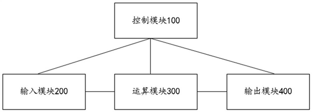
The invention discloses an optical signal processing method, a photonic neural network chip, and a design method of the chip. The optical signal processing method comprises the following steps: determining to-be-processed data and a target modulation range of an optical signal; modulating the initial input optical signal according to the to-be-processed data and the target modulation range to obtain a target input optical signal; performing parallel convolution calculation based on the target input optical signal to obtain a target output optical signal; and performing signal conversion on the target output optical signal to obtain an output electric signal, and executing corresponding processing operation according to the output electric signal. An operation module in the photonic neural network chip provided by the embodiment of the invention adopts an optical matrix multiplier, an accumulator and a nonlinear optical element to realize convolution parallel calculation of the same layer, so that the network operation efficiency is greatly improved, and the advantage of high operation speed of an optical simulation accelerator is fully embodied. And meanwhile, in cooperation with electrical storage and control, a multilayer optical neural network is constructed, and mature popularization of the optical neural network is promoted.

Description

technical field [0001] The present application relates to the field of photonic neural network, in particular to a method for processing optical signals, a photonic neural network chip and a design method thereof. Background technique [0002] Traditional computers are organized using a central processing unit, which is suitable for running sequential, digital, process-based programs. This architecture is very inefficient for distributed, massively parallel, and adaptive computational models, especially those used in artificial intelligence neural networks. Due to the large-scale parallel interconnection between neurons in the AI ​​model, it is not practical to use dedicated metal wiring to realize large-scale distributed hardware. Time-division multiplexing technology can only be used to exchange bandwidth for interconnectivity. [0003] But optical interconnects can avoid this trade-off, on the one hand due to the superior parallelism of photonic neural networks (ONNs), a...

Claims


Application Information

Patent Timeline
IPC IPC(8): G06N3/067
CPCG06N3/067
Inventor 晁银银董刚赵雅倩李仁刚姜金哲
Owner SUZHOU LANGCHAO INTELLIGENT TECH CO LTD
Learn More