Container flaw detection device and container production technology

A flaw detection device and container technology, applied in the field of flaw detection, can solve the problems of time-consuming flaw detection process, low efficiency, high labor intensity of operators, etc., and achieve the effect of reducing manual participation, reducing labor intensity, and improving flaw detection efficiency.

Pending Publication Date: 2022-02-18
ZHONGSHAN POLYTECHNIC
View PDF0 Cites 4 Cited by
  • Summary
  • Abstract
  • Description
  • Claims
  • Application Information

AI Technical Summary

Problems solved by technology

[0004] Because the radiation has certain harm to the human body, the existing container flaw detection device needs to be carried out in a flaw detection room with a good shielding effect. At the flaw detection station, the staff needs to carry out multiple preparations such as numbering, marking, and filming, and then start the flaw detection module to work after the staff leave the flaw detection room. The detection principle of the flaw detection module is to launch The ray passes through the container and is imaged on the imaging plate, thus showing the welding quality of the weld position. However, the flaw detection module can only irradiate part of the container, and the staff need to remove the flaw detection module after the flaw detection module stops. After flaw detection, turn the container to a certain position, and repeat the above work content, so as to carry out flaw detection on each part of the container. After a certain amount of flaw detection, the film needs to be developed, fixed, and dried to form a reliable film for review
The entire flaw detection process takes a long time, and the staff needs to enter the shielding room frequently, and the container needs to be transported many times, which is very cumbersome, inefficient, and the labor intensity of the operator is relatively high

Method used


Image

  • Container flaw detection device and container production technology
  • Container flaw detection device and container production technology
  • Container flaw detection device and container production technology

Examples


Embodiment Construction

[0053] Embodiments of the present invention are described in detail below, examples of which are shown in the drawings, wherein the same or similar reference numerals designate the same or similar elements or elements having the same or similar functions throughout. The embodiments described below by referring to the figures are exemplary only for explaining the present invention and should not be construed as limiting the present invention.

[0054] In the description of the present invention, it should be understood that when referring to orientation descriptions, such as terms "upper", "lower", "front", "rear", "left", "right", "vertical", "horizontal" ", "top", "bottom", "inner", "outer" and other indicated orientations or positional relationships are based on the orientations or positional relationships shown in the drawings, and are only for the convenience of describing the present invention and simplifying the description, rather than indicating Or imply that the devic...


PUM


Abstract

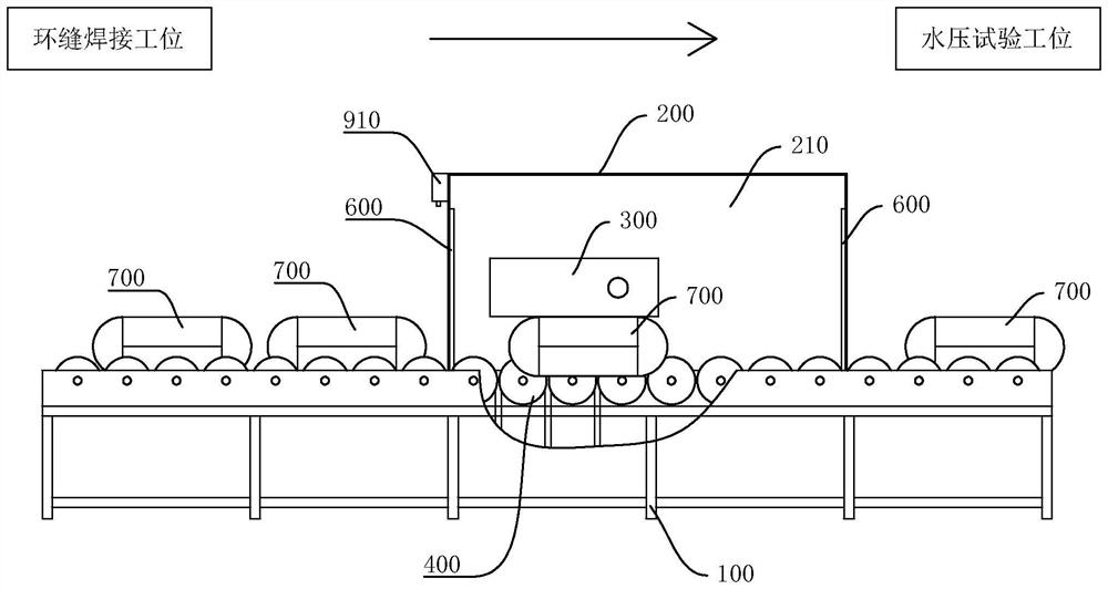
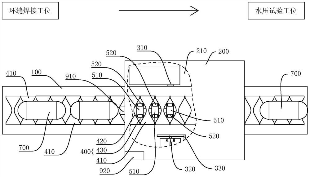
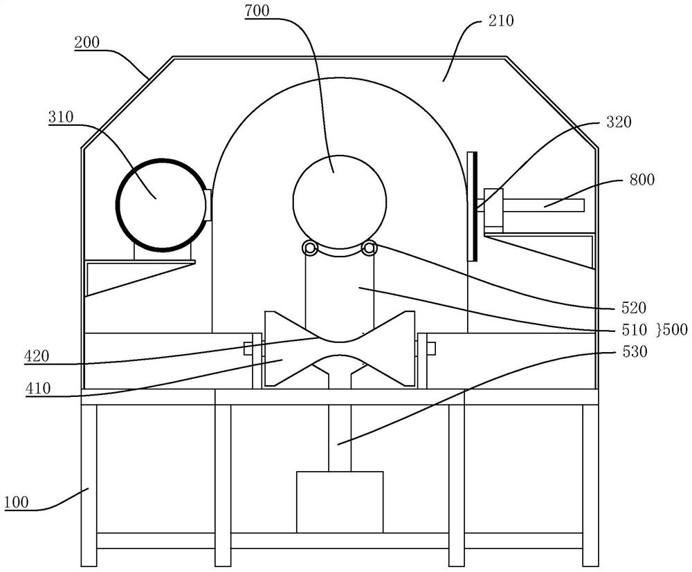
The invention discloses a container flaw detection device and a container production technology. The container flaw detection device comprises a base frame, a shielding shell internally provided with a flaw detection cavity, a flaw detection module, a conveying mechanism, a form positioning detection component, a deflection adjusting mechanism, an identification mechanism and a control module, the shielding shell is provided with an opening communicated with the flaw detection cavity, the flaw detection module is arranged on the base frame and located in the flaw detection cavity, the flaw detection module can detect different containers to be detected, part of the transmission mechanism is arranged in the flaw detection cavity through the opening, the transmission mechanism can transmit a to-be-detected container to get in and out of the flaw detection cavity, the form positioning detection component is used for obtaining welding seam position information of the to-be-detected container, the deflection adjusting mechanism can drive the to-be-detected container to rotate, and the control module is connected with the form positioning detection component, the transmission mechanism and the deflection adjusting mechanism so as to control the transmission mechanism and the deflection adjusting mechanism to operate according to the welding seam position information of the to-be-detected container. The flaw detection efficiency can be improved, and the safety of a user is guaranteed.

Description

technical field [0001] The invention relates to the technical field of flaw detection, in particular to a container flaw detection device and a container production process. Background technique [0002] In many sectors such as industry, civil, military, and many fields of scientific research, it is necessary to use pressure vessels to store and transport pressurized gas or liquefied gases. Pressure vessels need to be welded before they can be formed. The typical production process is as follows: [0003] After the longitudinal weld and girth weld of the container are welded, the container is transported to the flaw detection waiting area, and then transported from the waiting area to the flaw detection station for flaw detection. After the flaw detection is completed, it is transported to the flaw detection completion area. Transfer to the hydrostatic test waiting area. [0004] Because the radiation has certain harm to the human body, the existing container flaw detection...

Claims


Application Information

Patent Timeline
Patent Type & Authority Applications(China)
IPC IPC(8): G01N23/04G01N3/12B23K31/12
CPCG01N23/04G01N3/12B23K31/125G01N2223/03G01N2223/30G01N2223/629G01N2203/0019G01N2203/0048B23K2101/12
Inventor 姚胜南孙明慧李中帅温瀚桦邱伊玲苏铠欣林伊晴陈伟余庆东刘枝珠姚晨曦
Owner ZHONGSHAN POLYTECHNIC
Why Eureka
Try Eureka