Improved reflection mode dynode

A dynode and pattern technology, applied in dynodes, electron multiplier dynodes, electron multiplier tubes, etc., can solve problems such as detector failure

Pending Publication Date: 2022-02-18
艾德特斯解决方案有限公司
View PDF0 Cites 0 Cited by
  • Summary
  • Abstract
  • Description
  • Claims
  • Application Information

AI Technical Summary

Problems solved by technology

This charge accumulation may be caused by the integration of incident charges and the emission of secondary electrons, which leads to an uncontrolled change in the potential at the conversion surface and eventually leads to the failure of the detector.

Method used


Image

  • Improved reflection mode dynode
  • Improved reflection mode dynode
  • Improved reflection mode dynode

Examples


Embodiment Construction

[0093] The invention will be further described with reference to highly preferred embodiments relating to devices and methods for manufacturing devices. It should be emphasized that the examples in this section are strictly non-limiting in scope.

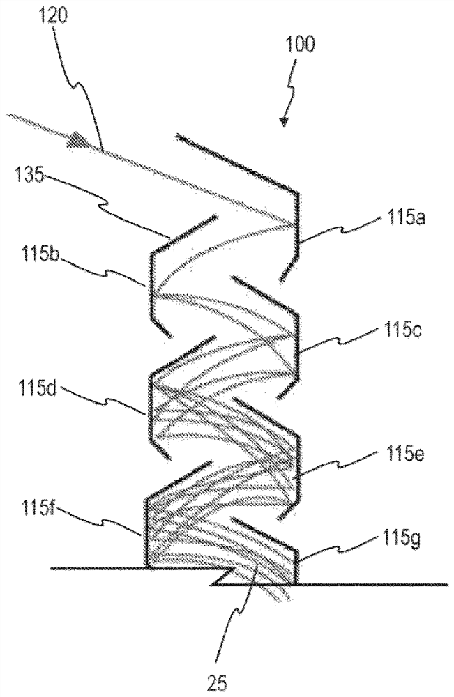
[0094] For highly preferred methods, refer to figure 1 , which highly diagrammatically shows the fabrication of a dynode (10) capable of operating in reflection mode.

[0095] The first step is to provide a substrate (15), which in this example is molybdenum, has a flat upper surface with dimensions 50mm x 50mm and a thickness of 1 mm. The substrates were cleaned by sonication and then exposed to oxygen plasma. After cleaning, the flat upper surface was spin-coated with nanodiamond particles.

[0096]The second step is to start growing a boron-doped polycrystalline diamond film (20) on one face of the substrate (15). The film was deposited by plasma-assisted chemical vapor deposition (PA-CVD) at a pressure of 70 Torr and a temp...


PUM

PropertyMeasurementUnit
thicknessaaaaaaaaaa
thicknessaaaaaaaaaa
particle sizeaaaaaaaaaa

Abstract

The present invention provides a device configured to convert or amplify a particle, the conversion or amplification being reliant on the impact of a particle on a surface of the device causing the emission of one or more secondary electrons from the same surface, wherein the device comprises a carbon-based layer capable of secondary electron emission upon impact of a particle. The surface may be used to convert, for example, an ion into an electron signal, or an electron signal into an amplified electron signal. The invention is particularly applicable to conversion or amplification dynodes.

Description

technical field [0001] The present invention relates to electron emitting surfaces capable of releasing electrons in response to the impact of particles including ions, neutral atoms, neutral molecules, protons, neutrons, electrons or photons. These surfaces can be used to convert eg ions into electronic signals, or convert electronic signals into amplified electronic signals. The invention is particularly suitable for conversion or magnification dynodes. Background technique [0002] In many scientific applications it is necessary to detect ions, neutral atoms, neutral molecules, protons, neutrons, electrons or photons. Typically, the detector consists of a first conversion surface (dynode) with which incident particles collide and emit secondary electrons, which are then amplified in the multiplication section. Alternatively, the first conversion surface may emit particles other than electrons interacting with the second conversion surface, and the second conversion surf...

Claims


Application Information

Patent Timeline
Patent Type & Authority Applications(China)
IPC IPC(8): H01J43/04H01J1/32
CPCH01J43/246H01J25/76C30B28/14C30B29/04C30B31/08C23C16/44C23C16/56C23C16/278C23C16/274H01J49/025H01J43/04C30B25/10C30B25/18C23C16/0272H01J1/32C23C16/0227C23C16/26C23C16/511C30B25/02C30B31/06H01J9/125H01J43/10
Inventor T·珊利W·希尔斯
Owner 艾德特斯解决方案有限公司
Why Eureka
Try Eureka