
Production equipment for photovoltaic round wire copper strip

A technology of production equipment and round wire, applied in metal processing equipment, metal rolling, metal rolling racks, etc., can solve the problems of increased processing defect rate, copper strip bending and dislocation, inconvenient use, etc., to reduce processing The effect of defective rate, avoiding distortion and expanding the scope of application

Pending Publication Date: 2022-02-22
ZHEJIANG TRUMHE NEW MATERIAL CO LTD
View PDF0 Cites 0 Cited by
  • Summary
  • Abstract
  • Description
  • Claims
  • Application Information

AI Technical Summary

Problems solved by technology

[0003] The existing round wire copper strip production equipment can only be applied to copper strips with a single outer diameter specification, and the scope of application is small; and it is difficult to adjust the positions of multiple independent rolling components in the calendering mechanism to be on the same straight line. As a result, the copper strip is prone to bending and misalignment during processing, which is inconvenient to use; at the same time, the lack of straightening function makes the round wire copper strip easily skewed into the rolling assembly, which in turn leads to distortion of the rolling section of the round wire copper strip Deformation or the gap between two adjacent rolling sections does not meet the requirements, resulting in an increase in the processing defect rate; in addition, multiple forming blocks in the drawing mechanism share a coolant recovery assembly, in order to cover each forming block, the size of the cooling liquid recovery component must be made larger, resulting in a larger volume of the entire drawing device; and in order to cover the cooling liquid recovery component, the amount of cooling liquid used is relatively large, but the actual effective usage is relatively small. The effective utilization rate of coolant is low and needs to be further improved

Method used


Image

  • Production equipment for photovoltaic round wire copper strip
  • Production equipment for photovoltaic round wire copper strip
  • Production equipment for photovoltaic round wire copper strip

Examples


Embodiment Construction

[0031] Unless otherwise defined, the technical terms or scientific terms used in the present invention shall have the usual meanings understood by those skilled in the art to which the present invention belongs. "First", "second" and similar words used in the present invention do not indicate any order, quantity or importance, but are only used to distinguish different components. "Comprising" or "comprising" and similar words mean that the elements or items appearing before the word include the elements or items listed after the word and their equivalents, without excluding other elements or items. Words such as "connected" or "connected" are not limited to physical or mechanical connections, but may include electrical connections, whether direct or indirect. "Up", "Down", "Left", "Right" and so on are only used to indicate the relative positional relationship. When the absolute position of the described object changes, the relative positional relationship may also change acc...


PUM


Abstract

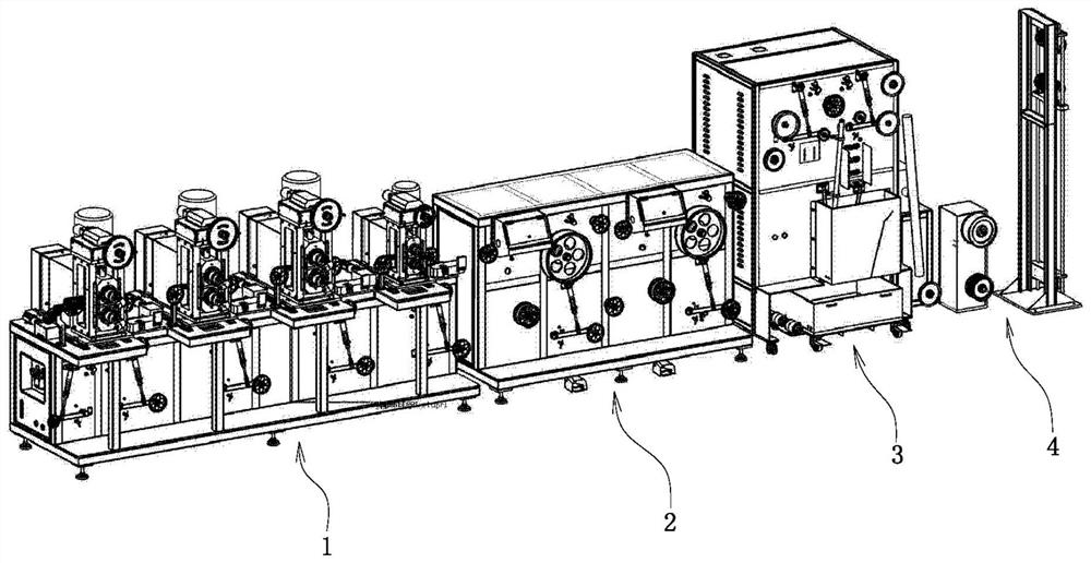
The invention relates to production equipment for a photovoltaic round wire copper strip. The production equipment comprises a calendering mechanism, a drawing mechanism, an annealing and cooling mechanism and a wire storage mechanism which are sequentially arranged in the material feeding direction; The calendering mechanism comprises a first cabinet body, a plurality of rolling assemblies which are transversely and sequentially arranged are arranged on the upper side of the first cabinet body, each rolling assembly is further provided with a guide assembly, and a straightening assembly comprises an input assembly and an output assembly; the input assembly and the output assembly are arranged on the outer sides of the left side block and the right side block correspondingly and arranged above a first buffering assembly and a second buffering assembly correspondingly; and the drawing mechanism comprises a second cabinet body, and a plurality of transversely-arranged drawing assemblies are arranged on the second cabinet body. The application range is widened, bending and dislocation of the copper strip in the processing process can be avoided so that use can be facilitated, meanwhile, the processing reject ratio is greatly reduced, and the effective utilization rate of cooling liquid is increased so that the production cost can be reduced.

Description

technical field [0001] The invention relates to a production equipment of a photovoltaic round wire copper strip. Background technique [0002] In the manufacture of photovoltaic equipment, welding strips must be used to connect the various circuit boards; the welding strips are made of round wire copper strips after repeated continuous rolling and continuous drawing, and then annealed. The welding strip needs to be sorted and transitioned by the wire storage mechanism before it can be reeled and produced, while the processing of the round wire copper strip is completed in the supporting production equipment. [0003] The existing round wire copper strip production equipment can only be applied to copper strips with a single outer diameter specification, and the scope of application is small; and it is difficult to adjust the positions of multiple independent rolling components in the calendering mechanism to be on the same straight line. As a result, the copper strip is pr...

Claims


Application Information

Patent Timeline
Patent Type & Authority Applications(China)
IPC IPC(8): B21B1/16B21B31/22B21F1/02B21C1/04B21C9/00
CPCB21B1/16B21B31/22B21F1/02B21C1/04B21C9/00
Inventor 孙益民邓琴
Owner ZHEJIANG TRUMHE NEW MATERIAL CO LTD
Learn More