Optical proximity correction method for corner-to-corner structure in layout

An optical proximity correction and diagonal technology, which is applied in the direction of optics, photographic process of pattern surface, and originals for photomechanical processing, etc., can solve the problem that the distance between the outer corner and the corner is not enough, and the distance between the inner graphics is not enough. , MRC error reporting and other issues to achieve the effect of reducing the risk of defects, reducing the risk of shrinkage or even falling off, and ensuring accuracy

Pending Publication Date: 2022-02-22
SHANGHAI HUALI INTEGRATED CIRCUTE MFG CO LTD
View PDF0 Cites 2 Cited by
  • Summary
  • Abstract
  • Description
  • Claims
  • Application Information

AI Technical Summary

Problems solved by technology

As we all know, the exposed shape of the square corner figure will become a circle, which will lead to insufficient distance to enclose the internal figure
[0004] At present, the method for solving the above-mentioned technical problems is to grow a circle around the corners of the graphics (such as figure 2 structure), but although this method can ensure that the distance contained inside meets the requirements, it cannot guarantee that the distance between the outer corners is far enough, and there is a risk of MRC error reporting ( figure 2 middle five-pointed star position)

Method used


Image

  • Optical proximity correction method for corner-to-corner structure in layout
  • Optical proximity correction method for corner-to-corner structure in layout
  • Optical proximity correction method for corner-to-corner structure in layout

Examples


Embodiment Construction

[0031] The present invention is further described below in conjunction with the accompanying drawings and embodiments.

[0032] The present invention discloses a method for angular layout of the optical proximity correction method of the corner structure, characterized by comprising the steps of:

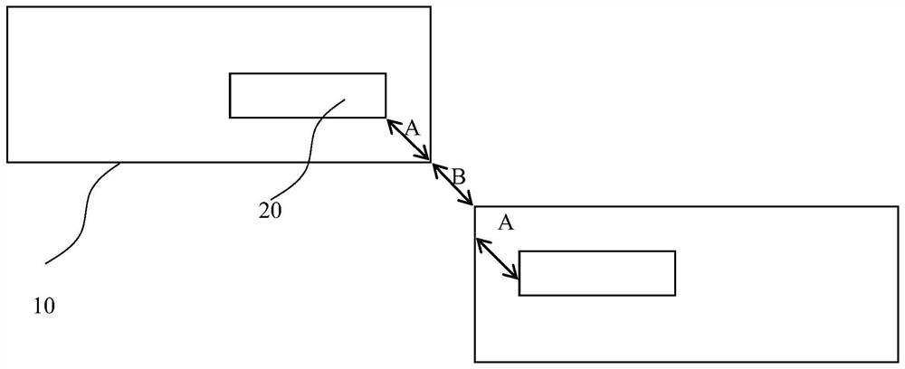
[0033] Step S1, the ion-implanted layer to identify the original pattern layout photolithography; the original pattern is a pattern of the angle corner structure.

[0034] Preferably, in step S1, the original pattern is a process when a layer pattern 10, when the covering layer of the process graphic pattern before the process layer on a substrate in a direction orthogonal projection 20.

[0035] Process front layer pattern may be the FIN (fin), or may be GATE (gate).

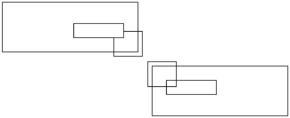
[0036] Step S2, the original corners of the original pattern, respectively, a cut angle; obtain gapped corner portion.

[0037] Preferably, in step S2, the vertical pitch P between each two opposite corner portions of th...


PUM


Abstract

The invention discloses an optical proximity correction method for a corner-to-corner structure in a layout. The optical proximity correction method comprises the following steps: S1, finding out an original pattern of an ion implantation layer photoetching layout, wherein the original graph is a graph of a corner-to-corner structure; S2, cutting off a corner at each of the original corners of the original graph, and obtaining a corner part with a notch; S3, on the basis of the pattern in the step S2, carrying out the correction processing to obtain a target pattern structure, wherein notches are formed in the corners of the target pattern, and protrusions are formed on the two adjacent corner edges of the corners of the target pattern; S4, performing model-based adjacent optical effect correction on the target graph to obtain a simulated photoresist contour line.

Description

Technical field [0001] The present invention relates to integrated circuit manufacturing process, in particular to a method of optical proximity correction for the angle of the corner structure layout. Background technique [0002] An optical proximity correction (OPC, Optical Proximity Correction) is a lithographic technique enhancement, image errors caused by impact. OPC mainly in the production of semiconductor devices used, is to ensure that the edges of the graphic design of the production process to give complete etching. The projected image appears irregularities, such as line width than the narrow or wide design, which can be compensated by changing the reticle imaged. Other distortions, such as rounded corners, by optical resolution tool constraints, is more difficult to make up. These distortions, if not corrected, could significantly change produced by the electrical circuit performance. Edge optical proximity correction by moving the reticle pattern or add additional ...

Claims


Application Information

Patent Timeline
Patent Type & Authority Applications(China)
IPC IPC(8): G03F1/36
CPCG03F1/36
Inventor 周启光于世瑞王飞舟
Owner SHANGHAI HUALI INTEGRATED CIRCUTE MFG CO LTD
Why Eureka
Try Eureka