Gravity compressed air energy storage system and method based on coal yard of thermal power plant

A technology for compressed air energy storage and thermal power plants, which is applied in energy storage, climate sustainability, and reduction of greenhouse gases. Enhance the flexibility of the power grid, reduce the loss of exergy, and have a long operating life

Pending Publication Date: 2022-02-25
XIAN TPRI BOILER ENVIRONMENTAL PROTECTION ENG CO LTD
View PDF0 Cites 2 Cited by
  • Summary
  • Abstract
  • Description
  • Claims
  • Application Information

AI Technical Summary

Problems solved by technology

Due to the poor safety of electrochemical energy storage, accidents of lithium battery energy storage power stations have occurred frequently in recent years; pumped hydro storage is limited by geographical conditions and has unpredictable impact on the ecological environment; the energy storage efficiency of gravity energy storage system is high, responsive Fast speed, low construction cost, and long running time, but its energy density is low and the construction scale is too large, so there is currently no commercial application
The traditional compressed air energy storage system has large energy storage capacity, high energy density, low construction and operation costs, and long operation time, but its efficiency is low and limited by geographical conditions, so it is difficult to apply in thermal power plants

Method used


Image

  • Gravity compressed air energy storage system and method based on coal yard of thermal power plant

Examples


Embodiment Construction

[0027] In order to enable those skilled in the art to better understand the solutions of the present invention, the following will clearly and completely describe the technical solutions in the embodiments of the present invention in conjunction with the drawings in the embodiments of the present invention. Obviously, the described embodiments are only The embodiments are a part of the present invention, not all embodiments, and are not intended to limit the scope of the present invention. Also, in the following description, descriptions of well-known structures and techniques are omitted to avoid unnecessarily obscuring the concepts disclosed in the present invention. Based on the embodiments of the present invention, all other embodiments obtained by persons of ordinary skill in the art without making creative efforts shall fall within the protection scope of the present invention.

[0028] The schematic diagrams of the structures according to the disclosed embodiments of th...


PUM


Abstract

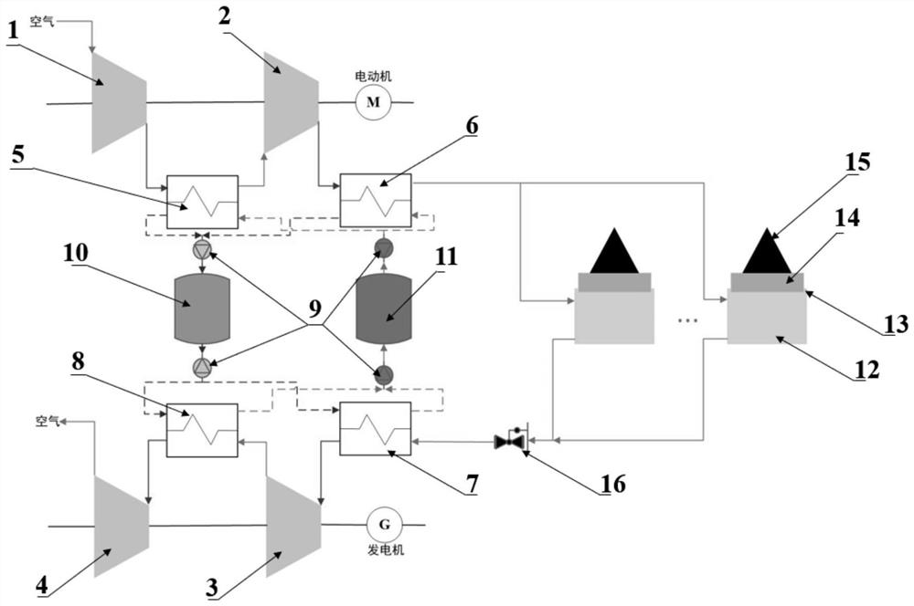
The invention discloses a gravity compressed air energy storage system and method based on a coal yard of a thermal power plant. In the system, a coal yard bearing plate is hermetically connected with the upper end of an air storage chamber; the input ends of the first-stage compressor and the second-stage compressor are connected with a motor, an outlet of the first-stage compressor is connected with a heat inlet of the first-stage interstage heat exchanger, and a heat outlet of the first-stage interstage heat exchanger is connected with an inlet of the second-stage compressor; an outlet of the second-stage compressor is connected with a heat inlet of the first-stage rear heat exchanger, and a heat outlet of the first-stage rear heat exchanger is communicated with the air storage chamber; the output ends of the first-stage expansion machine and the second-stage expansion machine are connected with a generator; an outlet of the air storage chamber is connected with a cold inlet of the second-stage front heat exchanger; an inlet of the first-stage expansion machine is connected with a cold outlet of the second-stage front heat exchanger, an outlet of the first-stage expansion machine is connected with a cold inlet of the second-stage inter-stage heat exchanger, and an inlet of the second-stage expansion machine is connected with a cold outlet of the inter-stage heat exchanger; and inlets and outlets of the heat storage tank and the cold storage tank are connected with the heat exchangers. The gravity energy storage technology and the compressed air energy storage technology are coupled.

Description

technical field [0001] The invention belongs to the technical field of energy storage, and in particular relates to a gravity compressed air energy storage system and method based on coal yards of thermal power plants. Background technique [0002] In recent years, with the accelerated transformation of the global energy structure to renewable energy and the proposal of my country's dual carbon goals, new energy is gradually developing into the main power source. According to estimates, the proportion of clean energy power generation is expected to reach 93% in 2060. The high proportion of renewable energy places higher requirements on the flexibility of grid regulation, and there is a huge demand gap for energy storage systems. On the other hand, in the future, a large number of low-parameter small thermal power plants will face the fate of being gradually shut down, while high-parameter large thermal power units will face problems such as deep peak regulation and flexible ...

Claims


Application Information

Patent Timeline
Patent Type & Authority Applications(China)
IPC IPC(8): F01K13/00F01K7/02F01K17/02F01K21/00F01K27/00F04B37/12F04B41/06F04B41/02
CPCF01K13/00F01K7/02F01K17/02F01K21/00F01K27/00F04B37/12F04B41/06F04B41/02Y02E60/16Y02E70/30
Inventor 牛国平李文锋贾兆鹏周飞邹小刚王一坤
Owner XIAN TPRI BOILER ENVIRONMENTAL PROTECTION ENG CO LTD
Why Eureka
Try Eureka