Supercharge Your Innovation With Domain-Expert AI Agents!

High-current ion implanter and method for controlling ion beam by using high-current ion implanter

一种离子植入、离子束的技术,应用在高电流离子植入器领域,能够解决保持等问题

Pending Publication Date: 2022-02-25
APPLIED MATERIALS INC
View PDF5 Cites 0 Cited by
  • Summary
  • Abstract
  • Description
  • Claims
  • Application Information

AI Technical Summary

Problems solved by technology

Galvanic isolation and power supplies are also limited to maintaining a specific voltage

Method used


Image

  • High-current ion implanter and method for controlling ion beam by using high-current ion implanter
  • High-current ion implanter and method for controlling ion beam by using high-current ion implanter
  • High-current ion implanter and method for controlling ion beam by using high-current ion implanter

Examples


Embodiment Construction

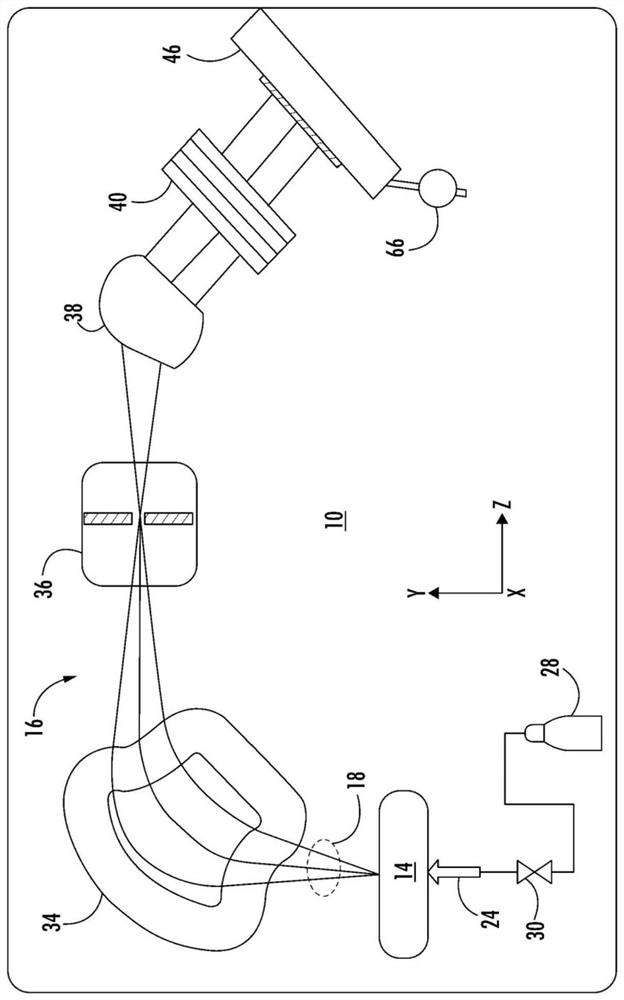
[0016] Ion implantation systems, electrostatic filters or lenses, and methods according to the present disclosure will now be explained more fully hereinafter with reference to the accompanying drawings, in which embodiments of the disclosure are shown. The ion implantation system, electrostatic filter, and method may be implemented in many different forms and are not to be considered limited to the embodiments described herein. Rather, these embodiments are provided so that this disclosure will be thorough and complete, and will fully convey the scope of the systems and methods to those skilled in the art.

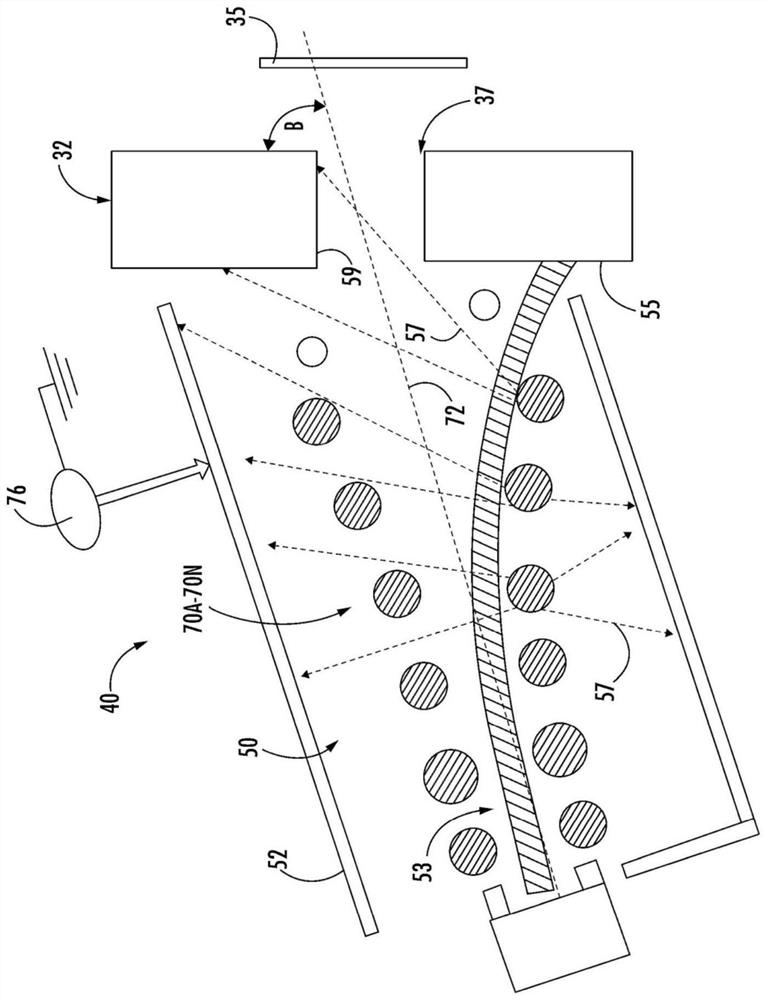
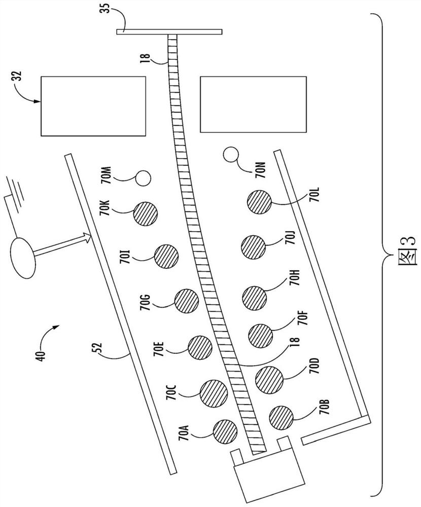
[0017] In view of the above-mentioned deficiencies identified by the prior art, provided herein is an ion implantation system that allows high current implanter operation with all the conventional benefits and extended maximum energy to cover a portion of the medium energy implanter operating space , Electrostatic filter and method. An exemplary electrostatic lens for an...


PUM


Abstract

Provided herein are approaches for increasing operational range of an electrostatic lens. The electrostatic lens of an ion implantation system may receive an ion beam from an ion source, and the electrostatic lens includes a first plurality of conductive beam optics disposed along one side of an ion beam line and a second plurality of conductive beam optics disposed along a second side of the ion beam line. The ion implantation system may further include a power supply in communication with the electrostatic lens, and the power supply is operable to supply a voltage and a current to at least one of the first and second plurality of conductive beam optics, wherein the voltage and the current deflects the ion beam at a beam deflection angle, and the ion beam is accelerated and then is decelerated within the electrostatic lens.

Description

[0001] Cross References to Related Applications [0002] This application is a non-provisional application of a pending U.S. Provisional Patent Application Serial No. 62 / 874,192 filed July 15, 2019, which is hereby incorporated by reference in its entirety. technical field [0003] The present disclosure relates generally to semiconductor processing, and more particularly to high current ion implanters. Background technique [0004] An ion implantation system may include an ion source and a series of beamline components. The ion source can include a chamber that generates ions. The ion source may also include a power source and extraction electrode assembly disposed adjacent to the chamber. The beamline assembly may include, for example, a mass analyzer, a first acceleration or deceleration stage, a collimator, and a second acceleration or deceleration stage. Similar to a series of optical lenses used to steer a beam of light, a beamline assembly can filter, focus, and st...

Claims


Application Information

Patent Timeline
Patent Type & Authority Applications(China)
IPC IPC(8): H01J37/12H01J37/317H01J37/05
CPCH01J37/12H01J37/3171H01J37/05H01J2237/04756H01J2237/24585H01J2237/057H01J2237/151H01J2237/12H01J2237/04735
Inventor 亚历山大·利坎斯奇常胜武法兰克·辛克莱安东尼勒·可雀帝艾立克·D·赫尔曼森克里斯多夫·坎贝尔
Owner APPLIED MATERIALS INC
Features
  • R&D
  • Intellectual Property
  • Life Sciences
  • Materials
  • Tech Scout
  • Unparalleled Data Quality
  • Higher Quality Content
  • 60% Fewer Hallucinations
Learn More