Blade type design method of gear workpiece end face continuous equidistant chamfering cutting tool

A technology of cutting tools and design methods, which is applied in the direction of gear tooth manufacturing tools, manufacturing tools, and components with teeth, etc., can solve the problems of cutting tool cutting edge design methods that have not yet been seen, difficult product update iterations, poor precision, etc. Achieve the effects of cutting state optimization, good numerical stability, and calculation stability

Active Publication Date: 2022-03-01
XI AN JIAOTONG UNIV
View PDF9 Cites 2 Cited by
  • Summary
  • Abstract
  • Description
  • Claims
  • Application Information

AI Technical Summary

Problems solved by technology

However, there is no design method for the cutting edge of special cutting tools for this kind of processing method.
Traditionally, the trial and error method is often used for complex cutting tool engineering, which has low efficiency and is difficult to meet the requirements. The accuracy is poor, and it is difficult to update and iterate products.

Method used


Image

  • Blade type design method of gear workpiece end face continuous equidistant chamfering cutting tool
  • Blade type design method of gear workpiece end face continuous equidistant chamfering cutting tool
  • Blade type design method of gear workpiece end face continuous equidistant chamfering cutting tool

Examples


Embodiment 1

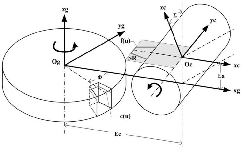
[0078] A method for designing a blade shape of a cutting tool for continuous equidistant chamfering of the end face of a gear workpiece, comprising the following steps,

[0079] Step 1, prepare the gear workpiece parameters required for cutting tool cutting edge calculation, including structural parameters and end face profile parameters;

[0080] The structural parameters of the gear workpiece include: the number of teeth zg=40, the helix angle βg=0, and parameters related to the tooth shape of the end face, such as the modulus of the involute gear 2mm, the pressure angle 20°, etc.;

[0081] The structural parameters of the gear end face chamfer include the depth of the end face profile chamfer along the gear axis h = 0.5mm;

[0082] Step 2, according to the traditional hob design experience, design the structural parameters of the cutting tool;

[0083] The cutting tooth structure parameters of the cutting tool include: number of teeth zc=8, right-handed rotation, helix ang...


PUM


Abstract

The invention discloses a blade design method of a gear workpiece end face continuous equidistant chamfering cutting tool, which comprises the following specific steps of: giving an included angle variable initial value phi between a gear tooth groove end face profile center line and a gear workpiece static coordinate system X axis; the angle theta c of the cutting tool rotating relative to the initial position when the cutting tool rotates around the rotation axis of the cutting tool is obtained through the installation parameters of the cutting tool and the gear workpiece, the variable initial value phi of the included angle and the transmission ratio i, and a transformation matrix Mcg and an inverse matrix Mgc from a cutting tool moving coordinate system to a gear workpiece moving coordinate system are obtained; a cylindrical gear tooth groove chamfering edge space curve c (u) is obtained, points on the gear tooth groove chamfering space curve c (u) are transformed to a cutting tool rake face SR through the transformation matrix Mcg, a cutting edge curve f (u) is obtained, and the cutting tool is machined through the obtained cutting edge curve f (u); the cutting tool with the designed cutting edge can ensure that chamfering structure cutting can be accurately carried out on the end face profile of the cylindrical gear under specified installation parameters and motion parameters.

Description

technical field [0001] The invention belongs to the field of cutting edges, in particular to a method for designing an edge shape of a cutting tool with continuous equidistant chamfering on the end face of a gear workpiece. Background technique [0002] As an important form of transmission, gear workpiece transmission is widely used in various types of machinery. The chamfering structure of the gear end profile is mainly used to remove the burr formed by the gear tooth profile processing, which is very important to ensure the long-term stable meshing movement of the gear. [0003] Extrusion molding and milling methods are often used for traditional gear workpiece end face profile chamfering. The extrusion molding method uses a chamfering cutter to mesh and roll with the edge of the gear, and the chamfering is formed by extrusion, but it will cause local surface deformation; the chamfering milling method uses a chamfering milling cutter to mill along the tooth profile track ...

Claims


Application Information

Patent Timeline
Patent Type & Authority Applications(China)
IPC IPC(8): B23F21/16
CPCB23F21/16
Inventor 贾康郭俊康洪军南凯刚
Owner XI AN JIAOTONG UNIV
Why Eureka
Try Eureka