Fused salt storage tank and fused salt electric heat storage long-time energy storage device

An energy storage device and electric heat storage technology, applied in the direction of valve device, steam engine device, valve operation/release device, etc., to achieve the effect of simple system, high efficiency of electric heating and thermoelectric conversion, and compact structure

Pending Publication Date: 2022-03-01
台州础能环境科技有限公司
View PDF0 Cites 0 Cited by
  • Summary
  • Abstract
  • Description
  • Claims
  • Application Information

AI Technical Summary

Problems solved by technology

[0014] At the same time, it solves the problem of flexibility in traditional thermal energy storage applications. This technology is safe, economical, and flexible. It also has the characteristics of strong adjustment ability, short construction period, low site selection requirements, and flexible construction scale. Salt electricity heat storage long-term energy storage technology will open up a new application scenario in the fields of industrial steam, heating and heating in residential areas, and "electric-thermal-electric" energy storage

Method used


Image

  • Fused salt storage tank and fused salt electric heat storage long-time energy storage device
  • Fused salt storage tank and fused salt electric heat storage long-time energy storage device
  • Fused salt storage tank and fused salt electric heat storage long-time energy storage device

Examples


Embodiment 1

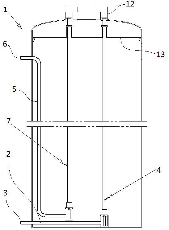
[0047] like figure 1 , figure 2 , image 3 As shown, a molten salt output branch pipe 2 is provided near the bottom of a molten salt storage tank 1, the outer port of the molten salt output branch pipe 2 is the first molten salt outlet 3, and an outlet shut-off valve 4 is arranged at the inner port The molten salt storage tank 1 is provided with a molten salt return branch pipe 5 extending from the top to the bottom of the storage tank, and the outer end of the molten salt return branch pipe 5 is a first molten salt inlet 6, and the first molten salt inlet 6 is in Above the molten salt liquid level line, an inlet shut-off valve 7 is arranged at the inner port of the molten salt return branch pipe 5 .

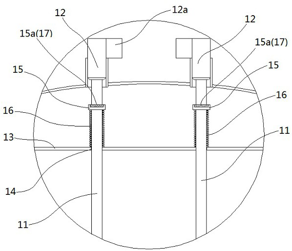
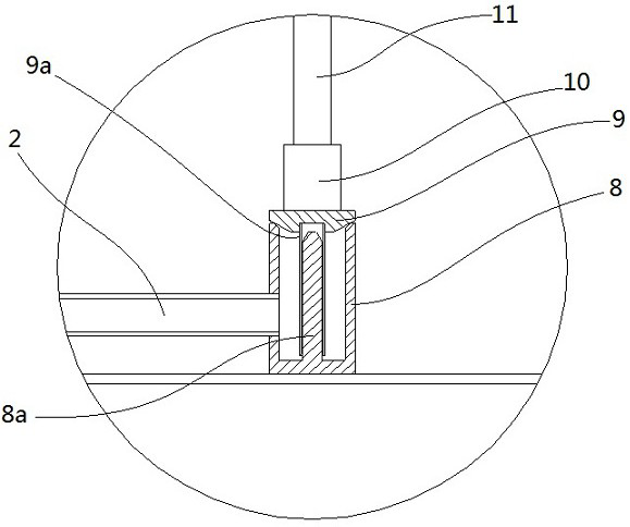
[0048] The outlet shut-off valve 4 and the inlet shut-off valve 7 have the same structure. From bottom to top, there are valve seat 8, valve flap 9, connecting frame 10, valve stem 11, and electric controller 12. Among them, the valve seat 8 and the melting valve The inner p...

Embodiment 2

[0054] like Figure 4 , Figure 5 and Figure 6 As shown, the molten salt storage tank 1 is also provided with a number of electric heating tubes 18, and a number of electric heating tube installation ports 19 are also provided on the cover plate 13. The electric heating tube installation port 19 matches; the rated voltage of the electric heating tube 18 is 6.6KV or 10KV.

[0055] Others are the same as in Embodiment 1, and will not be repeated here.

Embodiment 3

[0057] like Figure 7 , Figure 8 , Figure 10 , Figure 11 and Figure 12 As shown, a molten salt electric heat storage long-term energy storage device includes ten molten salt storage tanks 1, molten salt 20, molten salt output main pipe 21, molten salt return main pipe 22, molten salt pumping station 23, molten salt extraction Heater 24, electric control system 25.

[0058] In this embodiment, the total number of molten salt storage tanks 1 is ten, which are equally divided into two columns, with 5 in each column and arranged in a matrix at equal intervals; the molten salt output main pipe 21 is arranged in the middle of the two columns of molten salt storage tanks 1 Near the bottom, the molten salt return main pipe 22 is arranged near the top in the middle of the two rows of molten salt storage tanks 1, both of which are composed of a number of uniform specification three-way or four-way welded pipe joints and segmented molten salt pipes with U-shaped joints. The firs...


PUM


Abstract

According to the fused salt storage tank and the fused salt electric heat storage long-time energy storage device, the device can directly replace an existing coal-fired and gas-fired industrial steam boiler, and therefore centralized gas supply and heat supply in an industrial park through fused salt heat storage are promoted; meanwhile, after the fused salt electric heat storage long-time energy storage device is combined with a supercritical carbon dioxide generator set, a novel efficient'electricity-heat-electricity 'technical mode is generated, the fused salt electric heat storage long-time energy storage device can replace an existing pumped storage power station and an existing chemical energy storage station, and the fused salt electric heat storage long-time energy storage device becomes a large-capacity long-time energy storage technology. The system has the advantages of being compact in structure, simple in system, low in heat storage cost, high in heat release efficiency, small in system heat loss, high in electric heating and thermoelectric conversion efficiency, capable of achieving modularized, standardized, batched and factory production, safe, economical, flexible, high in adjusting capacity, short in construction period, low in site selection requirement, flexible in construction scale and the like.

Description

technical field [0001] The invention discloses a molten salt storage tank and a molten salt electric heat storage long-term energy storage device, belonging to the technical field of new energy storage. Background technique [0002] With the development of society, the deterioration of the global ecological environment is becoming more and more serious, and the control of carbon emissions is becoming more and more stringent. The adjustment of energy structure is accelerating towards the direction of green energy. Green energy such as solar energy and wind energy has received unprecedented attention. With the further increase in the proportion of new energy installed capacity, the measures taken to ensure the consumption of new energy mainly include: first, the deep peak-shaving transformation of coal power: reduce the minimum power generation; second, build new energy storage facilities: store new energy power generation, shift To the peak use of electricity, deep peak shavi...

Claims


Application Information

Patent Timeline
IPC IPC(8): F24H7/00F24H7/02F24H9/18F24H9/20F24H9/00F24H15/305F16K3/02F16K3/316F16K31/04F01K25/10F01D15/10
CPCF24H7/002F24H7/0216F24H9/18F24H9/00F24H9/20F16K3/0281F16K3/316F16K31/04F01K25/103F01D15/10
Inventor 李增清
Owner 台州础能环境科技有限公司
Why Eureka
Try Eureka