
Urban drinking water source monitoring system and monitoring method thereof

A monitoring system and water source technology, which is applied in the field of urban drinking water source monitoring system, can solve problems such as failure to warn, low detection efficiency, and inability of staff to know in time, so as to reduce work intensity and speed up efficiency

Inactive Publication Date: 2022-03-01
温莉虹
View PDF0 Cites 2 Cited by
  • Summary
  • Abstract
  • Description
  • Claims
  • Application Information

AI Technical Summary

Problems solved by technology

[0002] At present, drinking water source protection areas are divided into surface water drinking water source protection areas and groundwater drinking water source protection areas. In the protection of water source areas, manual testing is used on a regular basis. Not only is the detection efficiency low during the detection process, if When pollution occurs in one of the water source areas, it is impossible to find and deal with it in time. Since many water source areas are in remote places, the landforms vary from high to low. If pollution occurs, it is impossible to quickly find the polluted water source area. location, and within the water source area of ​​the division, if the water level of the water source changes significantly, the staff cannot know in time, and at the same time cannot warn people near the water source area that there is a problem with the water quality in the area

Method used


Image

  • Urban drinking water source monitoring system and monitoring method thereof
  • Urban drinking water source monitoring system and monitoring method thereof
  • Urban drinking water source monitoring system and monitoring method thereof

Examples


Embodiment Construction

[0029] The following will clearly and completely describe the technical solutions in the embodiments of the present invention with reference to the accompanying drawings in the embodiments of the present invention. Obviously, the described embodiments are only some, not all, embodiments of the present invention. Based on the embodiments of the present invention, all other embodiments obtained by persons of ordinary skill in the art without making creative efforts belong to the protection scope of the present invention.

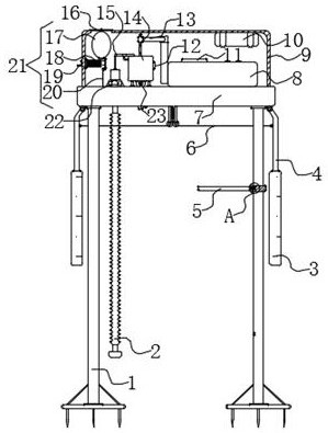
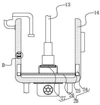
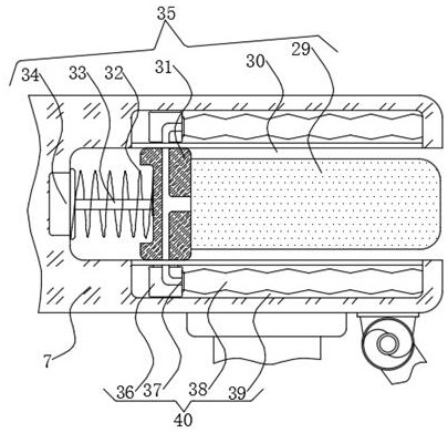
[0030] see Figure 1-6 , the present invention provides a technical solution: a monitoring system for urban drinking water sources, including a fixed platen 7, a fixed bottom bar 1 is arranged around the bottom of the fixed platen 7, and the fixed bottom bar 1 in the front end of the right side Both the upper end and the middle and lower ends are provided with a trigger mechanism 53, and the outer middle and upper end of the fixed bottom bar 1 on the left fron...


PUM


Abstract

The invention discloses an urban drinking water source monitoring system and a monitoring method thereof. The monitoring system comprises a fixed bedplate, fixed bottom rods are arranged on the periphery of the bottom end of the fixed bedplate, trigger mechanisms are arranged at the middle upper end and the middle lower end of the fixed bottom rod at the front end of the right side, and a mounting ring is arranged at the middle upper end of the outer part of the fixed bottom rod at the front end of the left side. When liquid water is injected into the detection water frame, a floating net plate and a cleaning lantern ring are driven to move upwards through buoyancy, the cleaning lantern ring penetrates through the lower end of the outer portion of a detection rod head, and when a water body in the detection water frame is drained away through an electromagnetic valve, the floating net plate moves downwards and drives the cleaning lantern ring to move downwards; if the detection rod head is detected, the bottom end of the outer part of the detection rod head is moved and rubbed through the cleaning lantern ring, so that the outer part of the detection rod head is automatically processed, and the situation that the detection result is not standard enough and errors are generated when the detection rod head is detected next time is prevented.

Description

technical field [0001] The invention relates to the field of drinking water sources, in particular to an urban drinking water source monitoring system and a monitoring method thereof. Background technique [0002] At present, drinking water source protection areas are divided into surface water drinking water source protection areas and groundwater drinking water source protection areas. In the protection of water source areas, manual testing is used on a regular basis. Not only is the detection efficiency low during the detection process, if When pollution occurs in one of the water source areas, it is impossible to find and deal with it in time. Since many water source areas are in remote places, the landforms vary from high to low. If pollution occurs, it is impossible to quickly find the polluted water source area. If the water level of the water source changes significantly, the staff cannot know it in time, and at the same time, they cannot warn people near the water s...

Claims


Application Information

Patent Timeline
IPC IPC(8): G01N33/18
CPCG01N33/18Y02A20/20
Inventor 温莉虹
Owner 温莉虹
Learn More