
Method and system for monitoring abnormity of wiring terminal of electric energy metering device

A technology for electric energy metering devices and terminal blocks, which is applied in measuring devices, electrical connection tests, and measuring electrical variables. It can solve problems such as difficulties in investigation and evidence collection, limited processing efficiency, and difficult handling by staff, so as to improve work quality and efficiency. The effect of improving intrinsic safety level and improving measurement accuracy

Pending Publication Date: 2022-03-01
国网重庆市电力公司营销服务中心 +1
View PDF0 Cites 0 Cited by
  • Summary
  • Abstract
  • Description
  • Claims
  • Application Information

AI Technical Summary

Problems solved by technology

[0005] Wiring errors: The current common method is to use a multimeter to test whether the two ends of the secondary circuit are normally connected when the installation is completed and the power is not turned on. Line test, the efficiency is low, and the quality is difficult to guarantee; another method is the integral test verification, that is, by measuring the voltage, current and phase angle of the electric energy meter, drawing a phasor diagram to judge whether there is a wrong connection, this method is more accurate. High, but manual implementation is still required, and the data comes from a set of measurements of phase separation and line separation, so it is difficult to guarantee sampling simultaneity and state universality;
[0006] Exceeding the limit of temperature and magnetic field strength: The current technical standards have clearly stipulated the temperature and magnetic field strength, but at the operational level, the temperature in the operating environment of the electric energy meter and the magnetic field strength of the environment are generally not tested. After the abnormality is generated and found, the environmental parameters are tested and recorded in the on-site operation and maintenance link. On the one hand, it has obvious hysteresis, and it often takes a long time to deal with the abnormality. On the other hand, it is not conducive to the investigation of the cause of the abnormality. processing, resulting in difficulties in investigation and evidence collection, or difficulties in the management of abnormal hidden dangers;
[0007] Voltage limit, current limit, reverse power, electricity theft risk: At present, data collection and judgment are mainly carried out through the electricity consumption information collection system. When these four types of abnormalities are found, relevant system functions will be called, work orders will be pushed, and staff will be reminded to deal with them , the problem and shortcoming of this method is that the power consumption information collection system adopts a regular sampling method, and the sampling period for different customers includes 15 minutes, 1 hour and 1 day, etc., so it does not have real-time performance. The information collection system adopts a single-point trigger method for abnormal judgment, that is, when any abnormality is found in the data of any measurement point, the work order is directly pushed, and each abnormal event is judged independently, and there is a lack of correlation verification. It is difficult for personnel to handle; finally, the system pushes work orders without information prompts, and can only be received after the staff log in to the system, which also limits the processing efficiency

Method used


Image

  • Method and system for monitoring abnormity of wiring terminal of electric energy metering device
  • Method and system for monitoring abnormity of wiring terminal of electric energy metering device

Examples


Embodiment 1

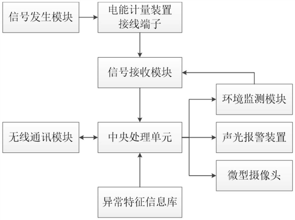
[0045] Such as figure 1 As shown, the present embodiment provides a monitoring system for abnormality of the connection terminal of an electric energy metering device, including a signal generating module 11, a signal receiving module 12, an environment monitoring module 13, a central processing unit 14, a wireless communication module 15, a miniature camera 16 and an acousto-optic Alarm device 17;

[0046] The signal generating module 11 and the signal receiving module 12 are respectively installed in the upper and lower connection terminals of the joint test junction box, and are respectively used to generate characteristic signals of specific frequencies and waveforms, and inject the characteristic signals into designated positions of the metering secondary circuit, and Identify and separate the characteristic signal from the electrical signal in the metering secondary circuit, and import the characteristic signal into the central processing unit 14;

[0047] The environme...


PUM


Abstract

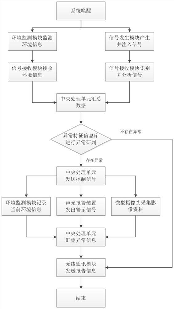
The invention discloses an electric energy metering device wiring terminal abnormity monitoring method and system, and relates to the technical field of electric energy monitoring, and the system comprises a signal generation module, a signal receiving module, an environment monitoring module, a central processing unit, a wireless communication module, a miniature camera and a sound-light alarm device. External equipment is additionally arranged at an electric energy meter combined test junction box, an intelligent local data acquisition and analysis function is configured, real-time optimization research and judgment of operation abnormity, environment abnormity, running state abnormity and electricity stealing risk of a wiring terminal of an electric energy metering device with the test junction box as a core are achieved, and according to the abnormity type and grade strategy, the electric energy metering device is optimized and judged. The warning information is reported in a differentiated manner in a reasonable manner, so that a worker can find abnormities as soon as possible and arrange operation and maintenance in order, and the installation quality and the operation quality of the electric energy metering device are improved.

Description

technical field [0001] The present invention relates to the technical field of electric energy monitoring, and more specifically relates to a method and system for abnormality monitoring of a terminal of an electric energy metering device. Background technique [0002] The electric energy metering device, especially the electric energy metering device connected through the transformer, is the direct basis for large and medium-sized electric power customers to conduct electric energy transactions. Therefore, it is necessary to conduct a comprehensive monitoring and analysis of the installation quality and operation quality of metering devices such as electric energy meters, test junction boxes, and secondary circuits, to detect abnormal events in time, to carry out test maintenance as soon as possible, and to rectify or eliminate them. [0003] The abnormal events described in the present invention are mainly aimed at the abnormalities related to the connection terminals of t...

Claims


Application Information

Patent Timeline
IPC IPC(8): G01R35/04G01R31/66G01R31/67G01D21/02
CPCG01R35/04G01R31/66G01R31/67G01D21/02
Inventor 张家铭郑可周峰杜杰冯凌肖冀常仕亮何珉谭时顺王雪松
Owner 国网重庆市电力公司营销服务中心
Learn More