Detachable ion beam accelerating tube

A technology of ion beams and accelerating tubes, applied in accelerators, electrical components, etc., can solve problems such as waste and achieve high acceleration gradients

Active Publication Date: 2022-03-01
SOUTHWESTERN INST OF PHYSICS
View PDF13 Cites 0 Cited by
  • Summary
  • Abstract
  • Description
  • Claims
  • Application Information

AI Technical Summary

Problems solved by technology

Moreover, once the dielectric strength of a certain insulating ring decreases, the entire ion accelerating tube needs to be replaced, resulting in waste

Method used


Image

  • Detachable ion beam accelerating tube
  • Detachable ion beam accelerating tube
  • Detachable ion beam accelerating tube

Examples


Embodiment Construction

[0038] The present invention will be described in further detail below in conjunction with specific examples, but the embodiments of the present invention are not limited thereto.

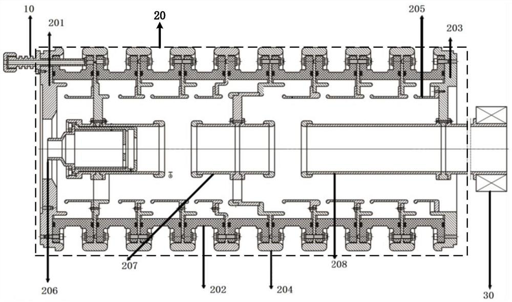
[0039] see figure 1 As shown, the detachable ion beam acceleration tube provided by the present invention includes: a high-voltage insulator 10 , an acceleration chamber 20 and a suppression magnet 30 .

[0040] Among them, the high-voltage insulator 10 is used to introduce initial convergence voltage into the ion beam accelerating tube. In practical application, the initial convergence voltage is about -30kV, and the initial convergence voltage is about 250kV DC high voltage as the reference ground, thus, the working voltage of the entire ion beam accelerating tube is about 280kV.

[0041] The acceleration cavity 20 is used to accelerate the ion beam drawn out by the ion source. The acceleration chamber 20 includes an input flange 201, a multi-stage insulating ring 202, and an output flange 203;...


PUM

PropertyMeasurementUnit
heightaaaaaaaaaa
thicknessaaaaaaaaaa

Abstract

The invention discloses a detachable ion beam accelerating tube, and the tube comprises a high-voltage insulator which is used for introducing an initial concentration voltage; the acceleration cavity comprises an input flange, a multi-stage insulating ring and an output flange which are connected through screws; each stage of insulating ring is of an integrally-formed 99 porcelain structure, and the outer wall of each stage of insulating ring is glazed; a grading ring is sleeved at the connecting position of every two stages of insulating rings, and the grading ring is connected with a corresponding shielding electrode in the accelerating cavity; an initial gathering electrode, a middle electrode and a ground electrode are sequentially arranged in the accelerating cavity through screws along the advancing direction of the ion beam; the initial polymerization electrode is connected with initial polymerization voltage through a high-voltage insulator, and the middle electrode is connected with a shielding electrode located in the middle of the interior of the acceleration cavity; the ground electrode is connected with the output flange and grounded; and the suppression magnet is arranged at the outlet of the output flange and is grounded. The ion beam accelerating tube is compact in structure, low in gas release amount in vacuum, capable of reaching ultimate vacuum in a short time, and detachable.

Description

technical field [0001] The invention belongs to the technical field of accelerators, and in particular relates to a detachable ion beam accelerating tube. Background technique [0002] The ion beam accelerating tube is an important part of the accelerator, mainly used to accelerate the ion beam generated by the ion source. [0003] In the prior art, the acceleration chamber of the ion beam acceleration tube is usually bonded by quartz sand and an insulating ring casted by epoxy resin. The insulating ring made of this material has a large amount of outgassing in a vacuum. When exposed to the atmosphere for a long time, the acceleration chamber of the ion beam acceleration tube needs several hours to reach the ultimate vacuum. Moreover, once the dielectric strength of a certain insulating ring decreases, the entire ion accelerating tube needs to be replaced, resulting in waste. Contents of the invention [0004] In order to overcome the above-mentioned problems in the prio...

Claims


Application Information

Patent Timeline
Patent Type & Authority Applications(China)
IPC IPC(8): H05H7/00
CPCH05H7/00
Inventor 孙雪静袁子豪龚少博赵光义王华杰
Owner SOUTHWESTERN INST OF PHYSICS
Why Eureka
Try Eureka