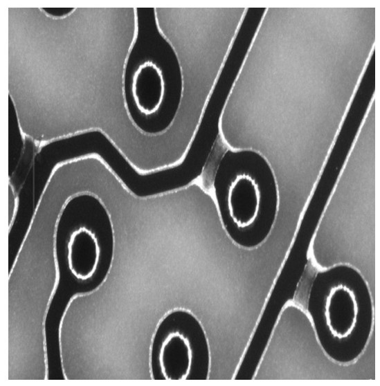
Circuit board pattern electroplating clamping film remover and pattern electroplating clamping film removing process

A graphic electroplating and circuit board technology, applied in the direction of electrical components, printed circuits, printed circuit manufacturing, etc., can solve the problems of film removal failure, increased production cost, and difficult removal of electroplating film, and achieve quality improvement, convenient operation, The effect of improving quality and yield

Active Publication Date: 2022-03-01
SHENZHEN BANMING SCI & TECH CO LTD
View PDF6 Cites 6 Cited by
  • Summary
  • Abstract
  • Description
  • Claims
  • Application Information

AI Technical Summary

Problems solved by technology

The contact surface between the clamped dry film and the film removal solution is small, and it is difficult to exchange the film removal solution, which leads to the failure of the film removal in the subsequent process. During etching, the copper layer in this area cannot be etched clean, causing short circuits, gaps, etc.
To solve this problem, the thickness of the dry film can be increased or the parameters of the electroplating equipment and copper electroplating light agent can be improved to improve the uniformity of the electroplated copper surface. However, the implementation of the above method will greatly increase the production cost, which is not conducive to the cost control of enterprises.
Most of the manufacturers now use self-prepared 3-5% NaOH solution to remove the film. The biggest advantage of using this method is low cost and simple operation, but the effect is not ideal.
NaOH solution has always had the problem of incomplete film removal and tin surface corrosion
The film stripping solutions currently used in the market, whether they are organic or inorganic, can only be used as stripping films for ordinary production boards in printed circuit board companies, but it is difficult to remove the electroplating film, which cannot affect the quality of production boards. The improvement brings help

Method used


Image

  • Circuit board pattern electroplating clamping film remover and pattern electroplating clamping film removing process
  • Circuit board pattern electroplating clamping film remover and pattern electroplating clamping film removing process
  • Circuit board pattern electroplating clamping film remover and pattern electroplating clamping film removing process

Examples


Embodiment Construction

[0029] The technical solutions of the present invention will be clearly and completely described below in conjunction with the embodiments of the present invention. Apparently, the described embodiments are part of the embodiments of the present invention, but not all of them. Based on the embodiments of the present invention, all other embodiments obtained by persons of ordinary skill in the art without making creative efforts belong to the protection scope of the present invention.

[0030] It should be understood that when used in this specification and the appended claims, the terms "comprising" and "comprises" indicate the presence of described features, integers, steps, operations, elements and / or components, but do not exclude one or Presence or addition of multiple other features, integers, steps, operations, elements, components and / or collections thereof.

[0031] It should also be understood that the terminology used in the description of the present invention is fo...


PUM


Abstract

The invention discloses a circuit board pattern electroplating sandwich film remover, and relates to the technical field of printed circuit board production, and the sandwich film remover is composed of the following components by the mass percentage: 5-20% of an organic alkali, 0.2-3% of a penetrant, 0.2-5% of a softening material, 0.05-10% of an accelerator, 0.05-1% of a tin surface bank protection agent, and the balance water. The sandwiched film remover can reduce the surface tension of a dry film, quickly permeate into a sandwiched film layer, soften and dissolve part of dry film slag, accelerate the fracture of a bond bridge between the dry films, enable the adhesive force of the dry films and a copper layer to disappear, and achieve the purpose of quickly and thoroughly removing the sandwiched film.

Description

technical field [0001] The invention relates to the technical field of printed circuit board production technology, in particular to a circuit board pattern electroplating clip film remover and pattern electroplating clip film removal process. Background technique [0002] In recent years, with the development of electronic equipment in the direction of lightness, thinness, shortness and smallness, the same lightness and thinness requirements have been put forward for printed circuit boards, which are characterized by more and more dense lines, and smaller and smaller line widths and line spacings. , High-density connection of lines, electrical reliability is getting stronger and stronger. At present, especially for express circuit board manufacturers, this requirement is particularly prominent. As a manufacturing process, graphic electroplating is an important process for thickening the circuit layer and hole plating after external light imaging. [0003] In the pattern e...

Claims


Application Information

Patent Timeline
Patent Type & Authority Applications(China)
IPC IPC(8): H05K3/18H05K3/22
CPCC25D5/48C25D5/022H05K3/0085H05K3/188H05K3/423H05K3/424
Inventor 李初荣韦金宇
Owner SHENZHEN BANMING SCI & TECH CO LTD
Why Eureka
Try Eureka