
System for synchronously measuring surface deformation and pressure distribution of rotating part

A technology for rotating parts and surface deformation, which is applied in the field of simultaneous measurement system for surface deformation and pressure distribution of rotating parts, to achieve the effect of controlling motion blur and clear and visible images

Pending Publication Date: 2022-03-08
CHINA ACAD OF AEROSPACE AERODYNAMICS
View PDF0 Cites 0 Cited by
  • Summary
  • Abstract
  • Description
  • Claims
  • Application Information

AI Technical Summary

Problems solved by technology

[0005] The purpose of the present invention is to provide a simultaneous measurement system for surface deformation and pressure distribution of rotating parts, which can solve the problems of surface deformation and pressure measurement of rotating parts;

Method used


Image

  • System for synchronously measuring surface deformation and pressure distribution of rotating part
  • System for synchronously measuring surface deformation and pressure distribution of rotating part
  • System for synchronously measuring surface deformation and pressure distribution of rotating part

Examples


Embodiment Construction

[0034] The technical solutions of the present invention will be clearly and completely described below in conjunction with the embodiments. Obviously, the described embodiments are part of the embodiments of the present invention, but not all of them. Based on the embodiments of the present invention, all other embodiments obtained by persons of ordinary skill in the art without making creative efforts belong to the protection scope of the present invention.

[0035] In describing the present invention, it is to be understood that the terms "center", "longitudinal", "transverse", "length", "width", "thickness", "upper", "lower", "front", " Back", "Left", "Right", "Vertical", "Horizontal", "Top", "Bottom", "Inner", "Outer", "Clockwise", "Counterclockwise", etc. or The positional relationship is based on the orientation or positional relationship shown in the drawings, which is only for the convenience of describing the present invention and simplifying the description, rather t...


PUM


Abstract

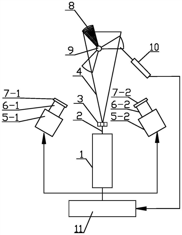
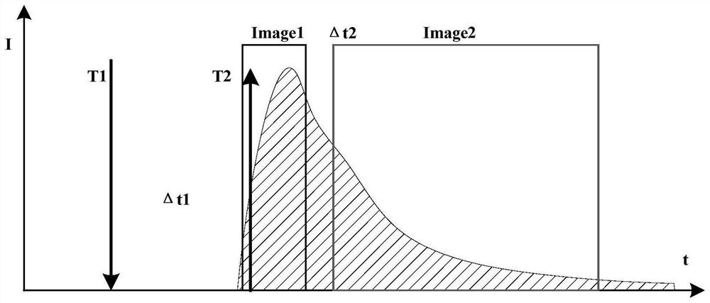
The invention relates to the technical field of rotating part surface deformation and pressure distribution measurement, in particular to a rotating part surface deformation and pressure distribution synchronous measurement system. The system comprises a laser light source module, an image acquisition module, a synchronous control module and a rotating part carrier, the laser light source module is a laser light source capable of outputting 10ns pulse width; the image acquisition module comprises two cross-frame CCD (Charge Coupled Device) cameras, and the two cross-frame CCD cameras are used for acquiring two images within a set time interval; the synchronous control module is used for providing a trigger signal of the laser light source module and an acquisition signal of the image acquisition module; the rotating part carrier comprises a rotating part to be measured, and the surface of the rotating part to be measured is provided with PSP coating and speckle mark points. The system effectively controls motion blur of the rotating part, so that an image is clear and visible; and phase locking of the high-speed rotating component is realized.

Description

technical field [0001] The invention relates to the technical field of measuring surface deformation and pressure distribution of rotating parts, in particular to a simultaneous measurement system for surface deformation and pressure distribution of rotating parts. Background technique [0002] Rotating machinery such as helicopter rotors, air and underwater propellers, compressor rotors, and turbine blades are widely used in aerospace as an important part of power propulsion systems. This kind of parts is characterized by high speed, and its surface pressure distribution and deformation are parameters that are generally concerned about. However, traditional measurement methods are difficult to apply to the measurement of the surface and space field of this type of moving and rotating body. For the complex flow field of rotating machinery There is a lack of intuitive and effective measurement methods for multi-physics parameters. [0003] Three-dimensional Digital Speckle C...

Claims


Application Information

Patent Timeline
Patent Type & Authority Applications(China)
IPC IPC(8): G01B11/16G01L11/02G01N21/64
CPCG01B11/16G01L11/02G01N21/6456
Inventor 王宏伟于靖波李晓辉任少洁黄湛康国剑
Owner CHINA ACAD OF AEROSPACE AERODYNAMICS
Learn More