Direct-connection magnetic coupling rotating shaft for electric spark forming machine

A magnetic coupling and forming machine technology, applied in the direction of electric processing equipment, metal processing equipment, accessory devices, etc., can solve the problems of high installation accuracy, affecting processing accuracy, inconvenient maintenance, etc., achieve long service life, improve reliability, Easy to install

Pending Publication Date: 2022-03-11
通用技术集团机床工程研究院有限公司 +1
View PDF13 Cites 0 Cited by
  • Summary
  • Abstract
  • Description
  • Claims
  • Application Information

AI Technical Summary

Problems solved by technology

[0003] The purpose of the present invention is to provide a direct-connected magnetically coupled rotating shaft used in electric discharge forming machines to solve the problems of vibration t

Method used


Image

  • Direct-connection magnetic coupling rotating shaft for electric spark forming machine
  • Direct-connection magnetic coupling rotating shaft for electric spark forming machine
  • Direct-connection magnetic coupling rotating shaft for electric spark forming machine

Examples


Embodiment Construction

[0052] The present invention will be described in detail below with reference to the accompanying drawings and examples. The principles and features of the present invention are described below in conjunction with the accompanying drawings. It should be noted that the accompanying drawings are only schematic diagrams provided for explaining the present invention, rather than real physical projection drawings; The embodiments and the features in the embodiments can be combined with each other. The examples given are only for explaining the present invention, not for limiting the scope of the present invention.

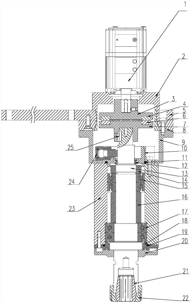
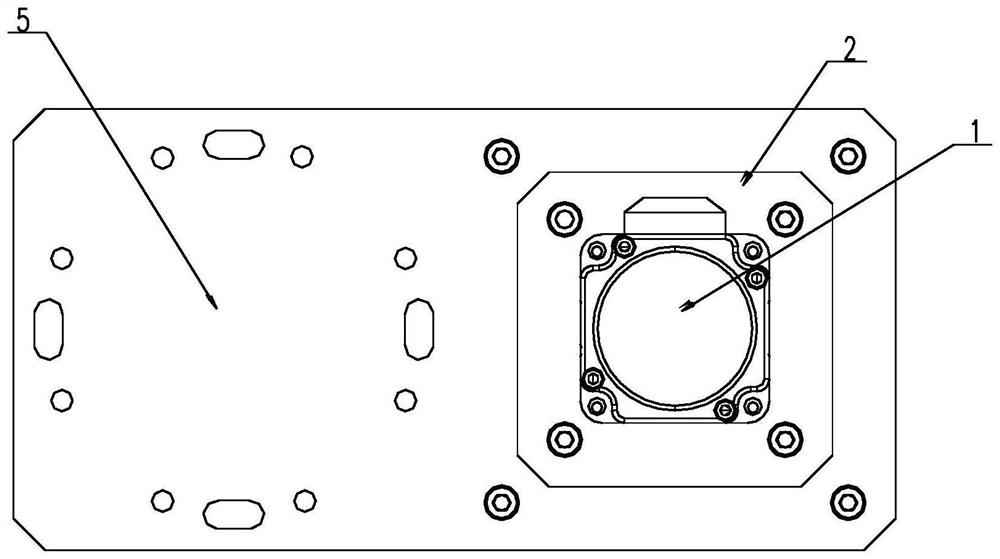
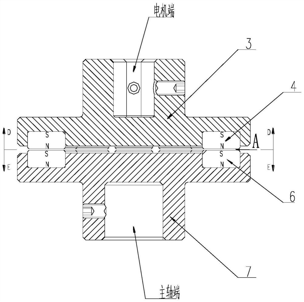
[0053] See eg Figure 1 to Figure 8 as shown, figure 1It is a schematic diagram of a cross-sectional structure assembly structure of a specific embodiment of a direct-connected magnetically coupled rotating shaft for an electric discharge forming machine provided by the present invention; figure 2 for figure 1 The top view structural schematic diagram of the specif...


PUM


Abstract

The invention discloses a direct-connection magnetic coupling rotating shaft for an electric spark forming machine. The direct-connection magnetic coupling rotating shaft comprises a motor. The motor end magnetic coupling transmission part consists of a motor connecting disc and an upper permanent magnet; the main shaft end magnetic coupling transmission part consists of a lower permanent magnet and a main shaft connecting disc; and the main shaft part consists of a main shaft, a locking nut, a first angular contact bearing, a spacer bush, a second angular contact bearing and a main shaft box. An electric spark forming machine tool numerical control system sends an instruction to control a servo motor through a servo driver, the servo motor rotates to drive a motor end magnetic coupling transmission part to rotate, a main shaft end magnetic coupling transmission part is driven to rotate, and torque transmission between the servo motor and a main shaft is achieved. Compared with a traditional mechanical connection transmission type rotating shaft, the rotating shaft has the advantages of being easy to maintain, simple and convenient to install and debug, energy-saving, environment-friendly, high in reliability, long in service life and the like. Vibration transmission can be effectively reduced, noise is lowered, and the device is used for an electric spark forming machine tool and widely applied to various machining fields.

Description

technical field [0001] The invention relates to the technical field of numerical control machining of electric discharge forming machine tools, in particular to a direct-connected magnetically coupled rotating shaft for electric discharge forming machines. Background technique [0002] With the development of modern manufacturing industry, the processing performance of EDM machine tools in various processing fields is getting higher and higher, the demand for multi-axis linkage processing is also gradually increasing, and the demand for rotating axes is also gradually increasing. Generally speaking, the rotating shaft adopts contact-type traditional mechanical transmission methods such as gear transmission and belt transmission for power transmission. There are problems such as vibration transmission affecting machining accuracy, excessive noise, high installation accuracy requirements, and inconvenient maintenance. Contents of the invention [0003] The purpose of the pre...

Claims


Application Information

Patent Timeline
IPC IPC(8): B23H11/00B23H1/00
CPCB23H11/00B23H1/00
Inventor 唐华王培德张佳强邓冬凤孙式玮吴迪贾靖宇席山山
Owner 通用技术集团机床工程研究院有限公司
Why Eureka
Try Eureka