Inverted T-shaped blind hole ceramic dielectric filter and special die thereof

A technology for ceramic dielectrics and filters, applied in molds, waveguide devices, electrical components, etc., can solve the problems of increasing the depth of blind holes, occupying surface area, increasing surface area, etc., to improve the dielectric constant, improve the Qf value, The effect of saving electricity

Active Publication Date: 2022-03-11
LIAONING YINGGUAN HIGH TECH CERAMIC CO LTD
View PDF8 Cites 0 Cited by
  • Summary
  • Abstract
  • Description
  • Claims
  • Application Information

AI Technical Summary

Problems solved by technology

However, the ceramic filter realizes its function by printing the circuit on the surface of the ceramic and welding it with the circuit board. In the prior art, a positive T-shaped hole is processed on the surface of the ceramic block, or multiple resonant holes or couplings are provided on one or more sides. The holes occupy the surface area of ​​the ceramic block. In order to ensure the function of the ceramic filter, the surface area of ​​the ceramic filter must be increased, and the depth of the blind hole will increase the thickness of the ceramic filter; the increase of the surface area and the thickness The increase of the ceramic filter leads to an increase in the overall volume of the ceramic filter, which is contrary to the requirements of 5G communication for the miniaturization and light weight of the filter

Method used


Image

  • Inverted T-shaped blind hole ceramic dielectric filter and special die thereof
  • Inverted T-shaped blind hole ceramic dielectric filter and special die thereof
  • Inverted T-shaped blind hole ceramic dielectric filter and special die thereof

Examples


Embodiment Construction

[0052] The present invention will be described in further detail below in conjunction with the accompanying drawings.

[0053] Specific implementation 1

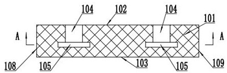
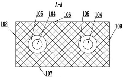
[0054] Such as figure 1 and 2 As shown, the inverted T-shaped blind hole ceramic dielectric filter of the present invention includes a hexahedral ceramic plate body 101, and the ceramic plate body 101 includes an upper surface 102, a lower surface 103, a front surface 106, a rear surface 107, a left surface 108 and a right On the surface 109, two upper holes 104 are arranged downwards on the upper surface 102 of the ceramic plate body 101, and lower holes 105 are respectively arranged below the two upper holes 104, and the diameter of the lower holes 105 is larger than the upper hole 104, further speaking, the diameter of the upper hole 104 is 3-4 mm, the diameter of the lower hole 105 is 6-9 mm, the upper hole 104 communicates with the lower hole 105, and the lower hole 105 communicates with the ceramic plate The lower s...


PUM

PropertyMeasurementUnit
diameteraaaaaaaaaa
diameteraaaaaaaaaa
diameteraaaaaaaaaa

Abstract

The invention discloses an inverted T-shaped blind hole ceramic dielectric filter and a special mold thereof, belongs to the technical field of ceramic dielectric filters, and solves the problems that a plurality of resonance holes or coupling holes are formed in a single surface or multiple surfaces of a ceramic block in the prior art, the surface area of the ceramic block is occupied, and the overall size is increased. The inverted-T-shaped blind hole ceramic dielectric filter is characterized in that two upper holes are downwards formed in the upper surface of the ceramic plate body, lower holes are formed below the two upper holes respectively, the diameter of each lower hole is larger than that of each upper hole, the upper holes and the lower holes are integrally formed into an inverted-T-shaped blind hole in an injection molding mode, and meanwhile a special mold for the inverted-T-shaped blind hole ceramic dielectric filter is provided. The inverted-T-shaped blind hole with the diameter of the lower hole larger than that of the upper hole and the lower hole only communicated with the upper hole is formed through gel casting, a good foundation is provided for sintering and silver plating in the follow-up process, the dielectric constant and the Qf value are improved, insertion loss is reduced, electric energy is saved, and the requirements of 5G communication for miniaturization, light weight, low cost and high performance of the ceramic dielectric filter are met.

Description

technical field [0001] The invention belongs to the technical field of ceramic dielectric filters, in particular to an inverted T-shaped blind hole ceramic dielectric filter and a special mold thereof. Background technique [0002] As one of the core components of the radio frequency unit, the filter is used to eliminate interference clutter, to allow useful signals to pass through without attenuation as much as possible, and to attenuate unwanted signals as much as possible. With the development of communication systems, especially 5G communication, the demand for miniaturization, light weight, low cost, and high performance of filters is obvious. Since ceramic dielectric filters use ceramic substrates to be plated with silver to form resonators, multiple resonators and The coupling between each resonator forms a filter, which can meet the requirements of 5G communication for smaller and smaller filter sizes. An important indicator of ceramic dielectric filters is low inse...

Claims


Application Information

Patent Timeline
Patent Type & Authority Applications(China)
IPC IPC(8): B28B7/16H01P1/20H01P11/00
CPCH01P1/2002H01P11/007B28B7/164
Inventor 李丽华杨爱英莫光光班洋
Owner LIAONING YINGGUAN HIGH TECH CERAMIC CO LTD
Why Eureka
Try Eureka