Closed cooling tower without waste water and valve cooling system

A technology of closed cooling tower and cooling chamber, which is applied in the direction of water shower cooler, scale removal and water softening, water/sewage treatment, etc. It can solve the threats to the safe and stable operation of the converter valve, increase the temporary stop time, and hidden dangers of water leakage, etc. question

Pending Publication Date: 2022-03-11
QUJING BUREAU OF SUPERVOLTAGE POWER TRANSMISSION CHINA SOUTHERN POWER GRID
View PDF16 Cites 0 Cited by
  • Summary
  • Abstract
  • Description
  • Claims
  • Application Information

AI Technical Summary

Problems solved by technology

Restricted by environmental protection requirements, the discharge of the discarded water from the external cooling system of the valve cooling system to natural waters is becoming more and more stringent. Some converter stations have closed the discharge of the discarded water from the external cooling water of the valve cooling system, so the concentration of ions in the external cooling water of the valve cooling system continues to rise. High, the fouling speed of the cooling water pipe outside the valve cooling system is greatly accelerated, resulting in a decrease in the cooling efficiency of the valve cooling system, causing an alarm for high cooling water temperature in the valve cooling system, which seriously threatens the safe and stable operation of the converter valve. Therefore, it is necessary to check the valve cooling system descaling of pipes
[0003] In the traditional technology, the descaling of valve cooling system pipes mainly adopts manual cleaning and adding antiscalant in the external cooling water. However, when descaling, high-voltage direct current shutdown is required, which increases the stoppage time and has poor effect on scale removal. , easy to cause damage to the coil, burying the hidden danger of water leakage

Method used


Image

  • Closed cooling tower without waste water and valve cooling system

Examples


Embodiment Construction

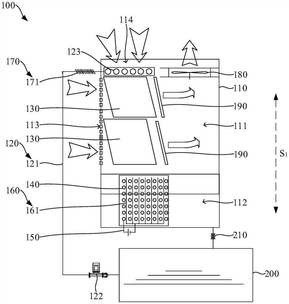
[0023] In order to make the above objects, features and advantages of the present invention more comprehensible, specific implementations of the present invention will be described in detail below in conjunction with the accompanying drawings. In the following description, numerous specific details are set forth in order to provide a thorough understanding of the present invention. However, the present invention can be implemented in many other ways different from those described here, and those skilled in the art can make similar improvements without departing from the connotation of the present invention, so the present invention is not limited by the specific embodiments disclosed below.

[0024] In describing the present invention, it should be understood that the terms "center", "longitudinal", "transverse", "length", "width", "thickness", "upper", "lower", "front", " Back", "Left", "Right", "Vertical", "Horizontal", "Top", "Bottom", "Inner", "Outer", "Clockwise", "Counte...


PUM


Abstract

The invention relates to an abandoned-water-free closed cooling tower and a valve cooling system.The abandoned-water-free closed cooling tower comprises a tower body, a spraying assembly, filler, a coil pipe, an electrochemical descaling device and a conductive part, the tower body is provided with a cooling cavity and a water tank, the spraying assembly is arranged at the top of the cooling cavity in the height direction of the tower body, and the filler is arranged in the water tank; due to the action of the filler, water sprayed out of the spraying assembly forms scale on the filler, and the concentration of ions such as Ca < 2 + >, Mg < 2 + >, OH <-> and HCO3 <-> entering water in the water tank can be reduced. The electrochemical descaling device in water prevents positively charged calcium ions and magnesium ions from scaling on the coil pipe according to the principle that like poles repel each other among electrons, the conductive part with the negative electrode connected between the coil pipes can adsorb the positively charged calcium ions and magnesium ions in the water tank, so that the scale is condensed on the negative electrode, the ion concentration in the water tank is reduced, and the scale removal efficiency is improved. And therefore, the scale on the coil pipe is reduced, and the working reliability of the valve cooling system is improved.

Description

technical field [0001] The invention relates to the technical field of DC converter valve cooling systems, in particular to a closed cooling tower without discarded water and a valve cooling system. Background technique [0002] The converter valves of conventional HVDC systems are all water-cooled. The valve cooling system is used to ensure that the operating temperature of the converter valves is within the normal range and is the core equipment of the converter station. The valve cooling system is mainly divided into an external cooling water system and an internal cooling water system, and the two systems are independent of each other. Restricted by environmental protection requirements, the discharge of the discarded water from the external cooling system of the valve cooling system to natural waters is becoming more and more stringent. Some converter stations have closed the discharge of the discarded water from the external cooling water of the valve cooling system, s...

Claims


Application Information

Patent Timeline
Patent Type & Authority Applications(China)
IPC IPC(8): F28C1/14F28F25/08F28F25/12F28F19/00C02F5/00
CPCF28C1/14F28F25/08F28F25/12F28F19/004C02F5/00F28C2001/145C02F2201/48
Inventor 刘百爽侯云川施礼兴陈佳欢代书龙
Owner QUJING BUREAU OF SUPERVOLTAGE POWER TRANSMISSION CHINA SOUTHERN POWER GRID
Why Eureka
Try Eureka