
Solid particle heating tank

A solid particle, heating tank technology, applied in heat treatment, chemical instruments and methods, chemical/physical processes, etc., can solve the problems of complex heating tank structure, inability to heat solid particles, insufficient fluidity of solid particles, etc. The effect of improving labor intensity, reducing the frequency of maintenance and/or replacement, and ensuring smoothness

Inactive Publication Date: 2022-03-15
内蒙古恒星化学有限公司
View PDF0 Cites 0 Cited by
  • Summary
  • Abstract
  • Description
  • Claims
  • Application Information

AI Technical Summary

Problems solved by technology

[0004] This application provides a solid particle heating tank, which is used to solve the problems of the existing heating tank with complex structure, inability to uniformly heat solid particles and insufficient fluidity of solid particles

Method used


Image

  • Solid particle heating tank
  • Solid particle heating tank
  • Solid particle heating tank

Examples


Embodiment 1

[0074] In the present embodiment, the solid particle heating tank operates as follows during specific work:

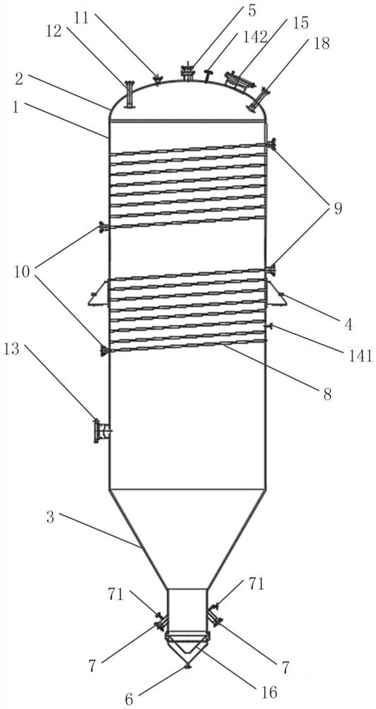
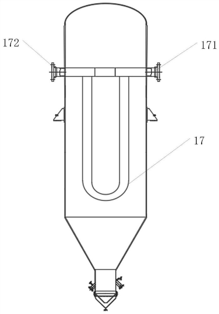
[0075] During specific use, take the synthesis of dimethyldichlorosilane monomer in organosilicon production as an example, silicon powder is passed into the heating tank from the solid particle feed port 5, nitrogen is passed into the nitrogen inlet 6, and the nitrogen flow rate is controlled as 800Nm 3 / h, nitrogen gas is evenly distributed inside the heating tank through the gas distributor 16, and silicon powder is in a flowing state in the heating tank at the same time. The coil 8 arranged on the outer wall of the tank body 1 is heated simultaneously with the U-shaped tube heat exchanger 17 inside the heating tank, so that the heating of the silicon powder is more uniform. The temperature rise rate of the silicon powder is 10°C / h, and the temperature of the heat transfer oil is maintained is 240°C. Open the first purge port 13 at regular intervals, and blow nitr...

Embodiment 2

[0077] In the present embodiment, the solid particle heating tank operates as follows during specific work:

[0078]During specific use, take the synthesis of dimethyldichlorosilane monomer in organosilicon production as an example, silicon powder is passed into the heating tank from the solid particle feed port 5, nitrogen is passed into the nitrogen inlet 6, and the nitrogen flow rate is controlled as 1000Nm 3 / h, nitrogen gas is evenly distributed inside the heating tank from bottom to top through the gas distributor 16, and silicon powder is in a flowing state in the heating tank at the same time. Using heat-conducting oil as the heating medium, and keeping the temperature of the heat-conducting oil at 260°C, the heat-conducting oil is passed into the coil tube 8 arranged on the outer wall of the tank body 1 and the U-shaped tube heat exchanger 17 inside the heating tank, and the silicon powder is heated by The inside and outside are heated at the same time, which makes t...


PUM


Abstract

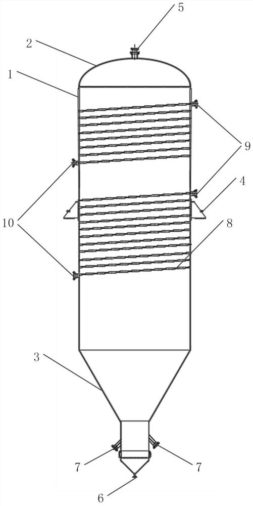
The solid particle heating tank comprises a tank body, an upper sealing head and a lower sealing head, the tank body is of a cylindrical structure, supporting frames are symmetrically arranged in the middle of the outer wall of the tank body, a solid particle feeding port is formed in the middle of the top of the upper sealing head, and a nitrogen inlet is formed in the bottom end of the lower sealing head; solid particle discharging ports are symmetrically formed in the two sides of the lower portion of the lower sealing head, a coil pipe is arranged on the outer side of the tank body, and a first heat conduction oil inlet and a first heat conduction oil outlet are formed in the two ends of the coil pipe. The solid particle heating tank provided by the invention is simple in structure, the purposes of storing and uniformly heating solid particles are achieved, the temperature of the solid particles entering a reactor is effectively increased, the influence on reaction when the solid particles enter the reactor is reduced, and the field working environment and the labor intensity are greatly improved.

Description

technical field [0001] The present application relates to the technical field of chemical equipment, in particular to a solid particle heating tank. Background technique [0002] With the development of the times, in order to meet the various needs of chemical production, there are more and more types of chemical equipment. The production of many chemical products has requirements for the temperature and pressure of materials. Heating tanks are often used in chemical production. The heating tank is a storage device used for temporary storage and heating of materials. After the material is preheated by the heating tank, it is then transported to the production equipment for production, which can improve the efficiency of chemical production. It can be seen that the quality of the heating tank has a direct impact on the production efficiency and product quality of chemical production. [0003] Most of the heating tanks currently used have problems such as complex structure a...

Claims


Application Information

Patent Timeline
Patent Type & Authority Applications(China)
IPC IPC(8): B01J6/00
CPCB01J6/00
Inventor 周文博渠国忠袁春光贾佳乐
Owner 内蒙古恒星化学有限公司
Learn More