
Soil pollution detection and treatment integrated device

A soil treatment and soil pollution technology, applied in sampling devices, soil material testing, restoration of contaminated soil, etc., can solve problems such as the inability to automatically conduct sampling, and achieve the goal of reducing soil residues, improving efficiency, and improving detection and treatment efficiency. Effect

Pending Publication Date: 2022-03-15
CHONGQING IND POLYTECHNIC COLLEGE
View PDF1 Cites 4 Cited by
  • Summary
  • Abstract
  • Description
  • Claims
  • Application Information

AI Technical Summary

Problems solved by technology

[0003] The purpose of the present invention is to at least solve one of the technical problems existing in the prior art, and provide an integrated device for soil pollution detection and processing, which can solve the problem that sampling cannot be performed automatically

Method used


Image

  • Soil pollution detection and treatment integrated device
  • Soil pollution detection and treatment integrated device
  • Soil pollution detection and treatment integrated device

Examples


Embodiment 1

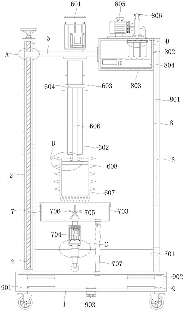
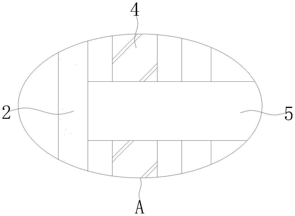
[0034] see Figure 1-6 The present invention provides a technical solution: a soil pollution detection and processing integrated device, including a soil treatment box 1, a sampling mechanism 6, a centrifugal mechanism 7, a detection mechanism 8 and a soil treatment mechanism 9, and the top of the soil treatment box 1 is fixedly installed with The support plate 2 and the vertical plate 3, a threaded rod 4 is rotated between the inner top and the bottom of the support plate 2, and one end of the threaded rod 4 runs through the support plate 2 and is fixedly connected with a rotating handle. The threaded rod 4 is provided with a horizontal plate 5 , the sampling mechanism 6 is arranged on the horizontal plate 5, and the sampling mechanism 6 includes a servo motor 601, a sleeve 602, a connecting sleeve 603, a mounting plate 604, a telescopic spring 605, a connecting plate 606, a sampling cylinder 607, a helical blade 608 and a rubber plate 609 , the centrifugal mechanism 7 is loc...

Embodiment 2

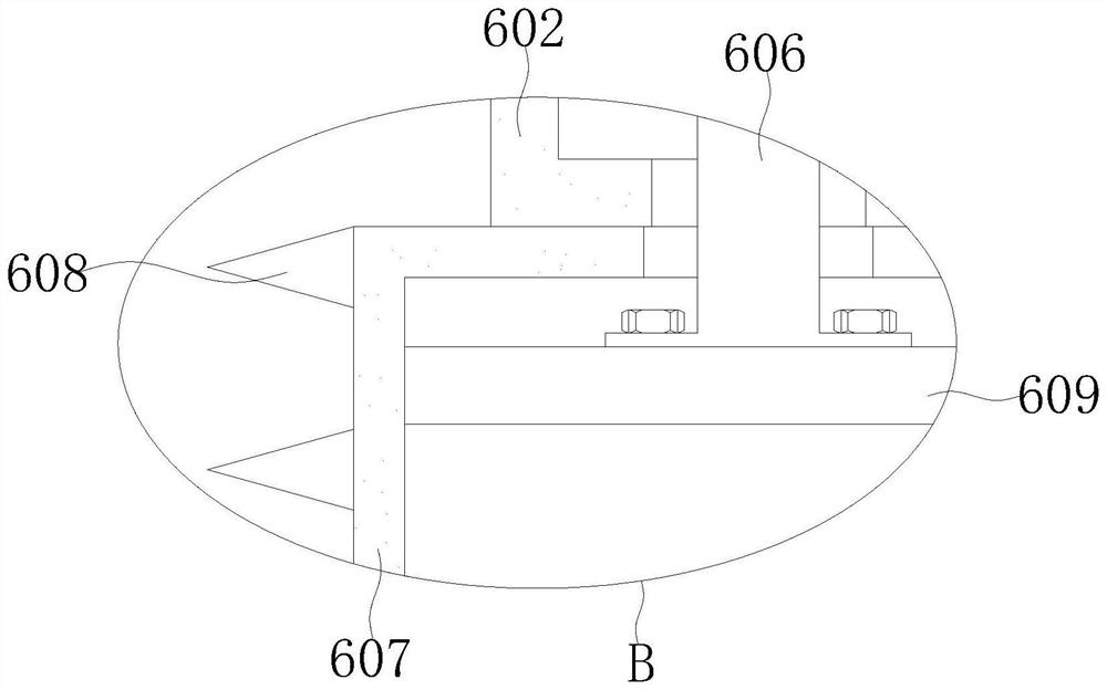
[0037] see Figure 1-6 On the basis of Embodiment 1, the bottom of the servo motor 601 is fixedly installed with the top of the horizontal plate 5, the top of the sleeve 602 is rotatably installed with the bottom of the horizontal plate 5, and the output shaft of the servo motor 601 extends to the horizontal through a coupling. The bottom of the plate 5 is fixedly connected with the top of the sleeve 602, the connecting sleeve 603 is sleeved on the outer wall of the sleeve 602, the outer walls of both sides of the mounting plate 604 are fixedly connected with the inner wall of the connecting sleeve 603, and one end of the telescopic spring 605 is connected to the The bottom of the sleeve 603 is fixedly connected, the other end of the telescopic spring 605 is fixedly connected with the outer wall of the sleeve 602 through a fixed block, the top of the connecting plate 606 is fixedly connected with the bottom of the mounting plate 604, the top of the sampling tube 607 is connecte...


PUM


Abstract

The invention discloses a soil pollution detection and treatment integrated device, and relates to the technical field of soil detection and treatment. The soil pollution detection and treatment integrated device comprises a soil treatment box, a sampling mechanism, a centrifugal mechanism, a detection mechanism and a soil treatment mechanism, a supporting plate and a vertical plate are fixedly mounted at the top of the soil treatment box, a threaded rod is rotatably mounted between the top and the bottom of the inner side of the supporting plate, and a transverse plate is arranged on the threaded rod. According to the soil pollution detection and treatment integrated device, a servo motor, a sleeve, a connecting sleeve, a mounting plate, a telescopic spring, a connecting plate, a sampling barrel, a spiral blade and a rubber plate are matched for use, so that the sampling barrel can be automatically driven to perform autorotation sampling, the automation degree is high, the workload of workers is reduced, and the working efficiency is improved; the soil can be quickly sampled, the soil detection and treatment efficiency is effectively improved, and the internal structure of the sampling barrel is simple.

Description

technical field [0001] The invention relates to the technical field of soil detection and processing, in particular to an integrated device for soil pollution detection and processing. Background technique [0002] Some existing soil pollution detection and processing integrated devices cannot automatically sample, which makes the soil sampling efficiency low, thereby reducing the efficiency of soil detection and processing, and when the soil is unearthed, it is easy to remain in the sampling cylinder. If there is a lot of soil, it is easy to mix with the soil of the secondary sampling, thereby reducing the accuracy of soil detection, such as the patent with the publication number CN110759402A, in which the dissolution and stirring of the soil is convenient for the detection of the soil, but this method cannot Automatic sampling makes the soil sampling efficiency low, thereby reducing the soil detection and processing efficiency, and the soil inside the sampling cylinder can...

Claims


Application Information

Patent Timeline
Patent Type & Authority Applications(China)
IPC IPC(8): G01N1/08G01N1/38G01N33/24B09C1/06B09C1/00
CPCG01N1/08G01N1/38G01N33/24B09C1/06B09C1/00
Inventor 梁丽
Owner CHONGQING IND POLYTECHNIC COLLEGE
Learn More