Full-automatic bundling and packing machine

A fully automatic, head-mounted technology, which is applied to the parts of strapping machinery, strapping materials, packaging, etc., can solve the problems of large mechanical wear of parts, failure to meet high-speed requirements, slow hydraulic response, etc., and achieve precise processing control and high The effect of high work efficiency and work precision

Pending Publication Date: 2022-03-18
广东科兴智能装备有限公司
0 Cites 0 Cited by

AI-Extracted Technical Summary

Problems solved by technology

[0004] However, with the development of society, all industries are pursuing high efficiency, especially for the assembly line. The hydraulic type cannot achieve a fast response speed due to the slow hydraulic response, so it cannot meet the ma...

Abstract

A full-automatic bundling and packing machine comprises a machine frame, a machine head module, a belt winding module, a belt advancing and retreating tensioning module, a belt feeding and penetrating module, a belt fence module and a belt rolling module, wherein the machine head module comprises a working group, the working group comprises a clamp arranged at the rear end of a belt conveying groove, a clamping die and a cutting die which are arranged on the two sides of the clamp respectively, a pressing die arranged at the lower end of the clamp, and a heating ironing head arranged on the front side of the clamp; the transmission set comprises a sliding connecting base used for enabling the clamp to move backwards to retreat from the belt conveying groove, a clamping connecting base used for driving the clamping die to eject upwards, a cutting connecting base used for driving the cutting die to eject upwards, a pressing connecting base used for driving the pressing die to eject upwards, and an ironing head swing rod used for driving the heating ironing head to be close to the clamp. The packaging machine has the characteristics of high speed, high efficiency and high reliability, meets the requirements of production lines of enterprises, and realizes rapid packaging of products.

Application Domain

Technology Topic

Image

  • Full-automatic bundling and packing machine
  • Full-automatic bundling and packing machine
  • Full-automatic bundling and packing machine

Examples

  • Experimental program(1)

Example Embodiment

[0035] Next, the technical scheme in the present application embodiment will be described in the present application embodiment, and it is clear that the described embodiments are merely the embodiments of the present application, not all of the embodiments. Understand, the present application is not limited by the example embodiments disclosed herein. Based on the embodiments in the present application, one of ordinary skill in the art is in the scope of the present application without making creative labor premistence.
[0036] In the description of the invention, it is to be understood that the terms "length", "width", "upper", "lower", "front", "post", "left", "right", "vertical", The orientation of the "horizontal", "top", "bottom", "inside", "outside", etc. is based on the orientation or positional relationship shown in the drawings, only for the convenience of the present invention and simplified description, not An indication or implies that the device or element must have a specific orientation, constructed and operated in a particular orientation, and thus is not to be construed as limiting the invention.
[0037] Moreover, the term "first", "second" is used only for the purpose of describing, and cannot be understood as an indication or implies a relative importance or implicitting the number of indicated techniques. Thus, features with "first", "second" may be indicated or implicitly including one or more of this feature. In the description of the invention, the meaning of "multiple" is two or more, unless otherwise specifically defined.
[0038] In an embodiment of the present invention, terms "mounting", "connected", "connection", "fixed", such as the term "mount", "connected", "connection", "fixed", unless otherwise express, unless otherwise specified, may be a fixed connection, or may be Disassemble the connection, or integral; it can be a mechanical connection or an electrical connection; it can be directly connected, or the intermediate medium can be indirectly connected, and the interaction between the two elements can be connected inside. The specific meaning of the above terms in the present invention can be understood in terms of specific cases.
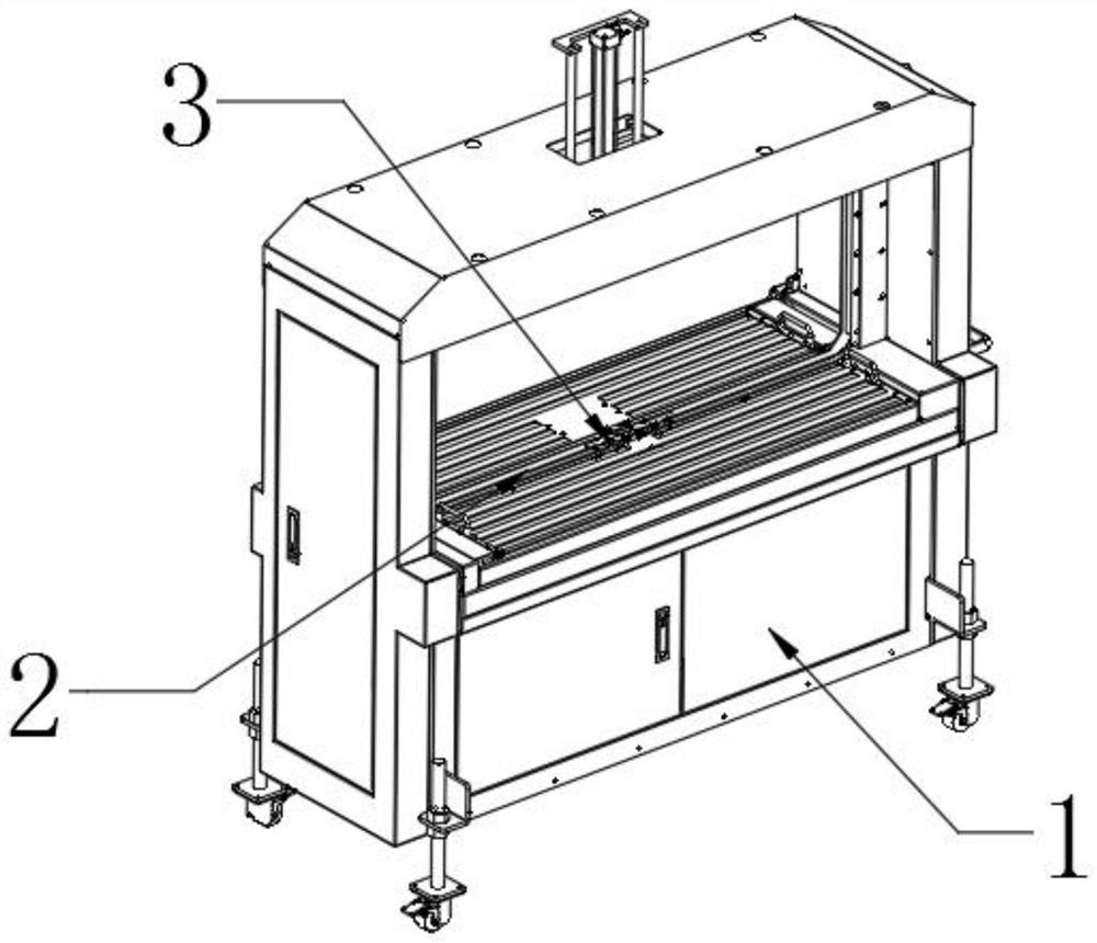
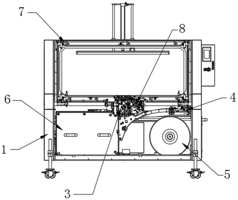
[0039] The present invention provides Figure 1 ~ 6 In the embodiment of the present invention, the fully automatic strapping the baler includes: a frame 1, a head module 3 mounted on the rack 1, a winding module 7, a tensioning module 8, and a belt tape module 4, Belt the module 6 and the band volume module 5;
[0040] The head module 3 is mainly used to achieve a series of bundling packages; the winding module 7 is mainly used to implement the band function, and the implementation will be bundled with a weekly arrangement;
[0041] The transfer belt tensioning module 8 is mainly used to send the package to the winding module 7. When packaging, timely exit excess packing belt, and tighten the adjustment packing belt according to the set tension; The packed belt is sent to a predetermined position in the conductive work of the initial web volume, and then the packing belt is sent to the belt module 6; The belt module 4 also has a brake function, that is, the brake state is maintained, fixed with a volume, and the brake is turned off, and the roll is driven by the belt strip module 4 to achieve the belt. The column module 6 is used to implement the storage belt, so that the belt-band module 4 can realize a single massive feed, when the packing strip in the column module 6 is insufficient, trigger the belt-band module 4 to send belt.
[0042] in:
[0043] The windband module 7 includes:
[0044] The arched bracket 71 mounted on the working surface of the rack 1 is disposed in the frame 1 working surface and the delivery belt groove 2 on the end face of the bracket 71; the head tail of the groove 2 is connected to form a ring structure; The inner arrangement is provided for the guide mechanism 72 for taking the strip along the tank 2; the guiding mechanism 72 can drive the feed belt into the delivery tank 2 to wind the tank 2;
[0045] The head module 3 includes:
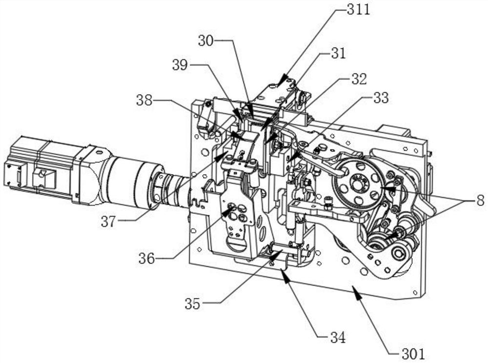
[0046] Working group, including: clamp 30 disposed on the rear end of the tank 2 and the clamping die 39 and the cut film 32 respectively disposed on both sides of the clamp 30, disposed on the lower end of the clamp 30, disposed on the clip. Heating iron 38 on the front side of the pliers;
[0047] The transmission group comprises: a sliding seat 311 for realizing the clamp 30 backward exiting the delivery belt groove 2, is used to drive the clamping seat 37 on the top of the clamping mode 39 for driving the cutting film 32 top. Cutting the connecting seat 33 for a pressing reagent 316 for driving the upper top of the press mold 31 and a hot head pear rod 36 for driving the heated pneumper 38 to the clamp 30;
[0048] The power group, including: camshaft 314 for providing power and cam shaft 314 by the cam servo motor 312; the cam servo motor 312 and the cam shaft 314 achieve drive cooperation by the reducer 313;
[0049] The cam shaft 314 is a multi-stage structure, respectively, respectively, the joint 31, the clamping seat 37, the cutting seat 33, the compression link 316, and the pressing joint 31, respectively, form five sets of trunk cam transmission structures;
[0050] Before processing, the bundled strip is placed in the belt roll module 5;
[0051] During the process, the strap of the strap is entered on the working surface of the rack 1; brought by the strapping strip in the strap in the belt strip module 4; the packed tension module 8 will be brought into the package In the delivery tank 2 of the module 7; the feed tape is fed along the feed tank along the feed tank by the guide mechanism 72 in the winding module 7.
[0052] The rear cam shaft 314 is driven by the cam servo motor 312 by the reducer 313; during the rotation of the cam shaft 314; the cam shaft 314 is pushing the clamp 30, clamp the head tail of the strap, and then drive the cutting film 32 The top will be cut in the back of the strap; the clamping die 39 upper top clamping the strap simultaneous clamp 30 reset release the strapping belt; by the heating iron 38 heats melt to the tail of the strap together and by the compression die 31 Compact.
[0053] Further, the belt belt module 4 includes a conductive roller 46 and a belt conveying group; and the upper guide plate 41 and the lower guide plate 45 disposed between the conductive roller 46 and the belt conveying wheel group. ;
[0054] The belt conveying wheel group includes: a driven wheel 43 driven by the drive motor and the driven wheel 44 in contact with the drive wheel 43; the active wheel 43 is formed between the driven wheel 44;
[0055] A cross-belt gap is formed between the upper guide plate 41 and the lower guide plate 45, the conductive roller 46, the over-band gap, and the tape gap are formed into the belt line.
[0056] Further, the apparatus further includes: a mounting template 301 for fixing the mounting machine head module 8, and the mounting template 301 is prepared on the mounting template 3 and the moving reticle tension module 8 for pre-preparation. Installed mounting groove 302.
[0057] Further, the drive group of the head module 3 also includes:
[0058] Used to secure the head module 3 in the mounting frame 34 on the mounting template 301;
[0059] A pair of vertically upwardly extending guide slide 315 is mounted on the mount 34;
[0060] The two sides of the compression link 316 are each nested on the guide slide 315, respectively; the clamping seat 37 and the cutting seat 33 on both sides also correspond to a guide slider 315 mounted on the same side, respectively; from the cam The shaft 314 drives the compression link 316, the clamping link 37 and the cutting seat 33 slide along the guide slider 315;
[0061] The clamping link 37 and the cutting connecting seat 33 are also connected between the holder 34, and a re-step spring 317 is provided, and the rear return spring 317 pulls the clamping seat 37 and the cutting seat 33 fallback return.
[0062] Further, the lower end of the holder 34 is also provided with a rotating link 35 of a laterally disposed.
[0063] The lower end of the hot head pear rod 36 is hinged to the rotating link 35, and the cam shaft 314 is sweded in the direction of the rotating link 35 toward the clamp 30.
[0064] It is also shown that in this article, relationship terms such as the first and second, etc. are only used to distinguish an entity or operation with another entity or an operational area, not necessarily or implies these entities or operations. There is any such actual relationship or order. Moreover, the term "comprising", "comprising" or any other variable is intended to cover non-exclusive contained, thereby enabling a process, method, article, or device including a series of elements, not only those elements, but also not expressly listed. Other elements, or elements that are also inherent to such processes, methods, items, or equipment. In the absence of more restrictions, the elements defined by the statement "include a ...", and there is no additional same elements in the process, method, item, or apparatus including the element.
[0065] The above description of the disclosed embodiments will be made or used in the art. A variety of modifications to these embodiments will be apparent to those skilled in the art, and the general principles defined herein may be implemented in other embodiments without departing from the spirit or scope of the present application. Thus, the present application will not be limited to the embodiments shown herein, but rather consistent with the widest range of the principles and novel features disclosed herein.

PUM

no PUM

Description & Claims & Application Information

We can also present the details of the Description, Claims and Application information to help users get a comprehensive understanding of the technical details of the patent, such as background art, summary of invention, brief description of drawings, description of embodiments, and other original content. On the other hand, users can also determine the specific scope of protection of the technology through the list of claims; as well as understand the changes in the life cycle of the technology with the presentation of the patent timeline. Login to view more.

Similar technology patents

Classification and recommendation of technical efficacy words

  • Low application cost
  • Improve work efficiency

Opencast mine end slope near-slope mining method

ActiveCN103133003AReduce stripping ratioLow application costOpen-pit miningSlope stabilityOpen-pit mining
Owner:CHINA UNIV OF MINING & TECH

Improved novel energy automobile charging device

Owner:XIAMEN YINLV JIEYUAN ENVIRONMENTAL PROTECTION TECH CO LTD
Why Eureka
Try Eureka