Supercharge Your Innovation With Domain-Expert AI Agents!

Mud-sand separation and oil sludge dehydration drying treatment equipment and treatment process

A technology of treatment equipment and treatment process, which is applied in the directions of dehydration/drying/concentrated sludge treatment, water/sludge/sewage treatment, sludge treatment, etc. High cost and other issues, achieve the effect of realizing resource reuse, improving processing efficiency and improving economy

Pending Publication Date: 2022-03-18
山东畅庆环保科技有限公司
View PDF0 Cites 0 Cited by
  • Summary
  • Abstract
  • Description
  • Claims
  • Application Information

AI Technical Summary

Problems solved by technology

However, the distribution of the heating furnace in the pyrolysis method is unreasonable, the thermal efficiency is not high, the equipment is complicated, the pyrolysis control is difficult, the operating cost is high, and the processing capacity is low.

Method used


Image

  • Mud-sand separation and oil sludge dehydration drying treatment equipment and treatment process
  • Mud-sand separation and oil sludge dehydration drying treatment equipment and treatment process

Examples


Embodiment 1

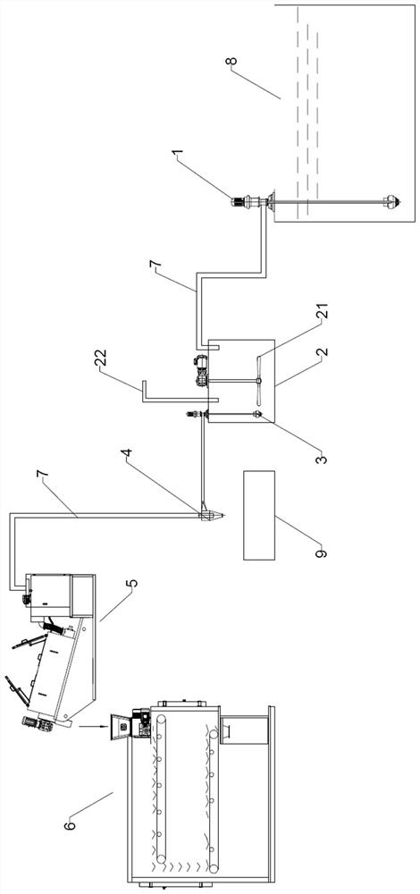
[0031] Such as figure 1 The mud-sand separation and sludge dehydration and drying treatment equipment shown includes a submersible sand mining pump 1, a sand washing tank 2, a submersible pump 3, a cyclone 4, a dehydrator 5, and a drying machine 6. The submersible sand mining pump 1 The output end of the submersible pump 3 is connected to the sand washing tank 2 through the delivery pipeline 7, the input end of the submersible pump 3 is arranged in the sand washing tank 2, and the output end of the submersible pump 3 is connected to the feed port of the cyclone 4 through the delivery pipeline 7 The overflow port of the cyclone 4 is connected to the feed port of the dehydrator 5 through the delivery pipe 7, and the discharge port of the dehydrator 5 is connected to the feed port of the drying machine 6.

[0032] Wherein, the input end of the submersible sand mining pump 1 is set in the oil sludge tank 8 .

[0033] Moreover, the sand washing tank 2 is provided with a stirring p...

Embodiment 2

[0037] The treatment process of the mud-sand separation and oil sludge dehydration and drying treatment equipment described in embodiment 1 comprises the following steps:

[0038] ① Use the submersible sand mining pump 1 to pump the sludge from the sludge tank 8 to the sand washing tank 2;

[0039] ②Start the stirring paddle 21, and at the same time inject hot water with a water temperature of 40-50°C into the sand washing tank 2 through the hot water injection pipe 22. The stirring paddle 21 rotates at a speed of 200 rpm. mix;

[0040] ③The sludge water mixed in step ② is pumped into the cyclone 4 through the submersible pump 3, and the sludge water is driven to rotate by the guide vanes in the cyclone 4. The bottom of the cyclone 4 is discharged into the sand storage tank 9; the sludge water without sand shrinks in the cyclone 4 and flows to the center, and is discharged upward from the overflow port into the dehydrator 5;

[0041] ④The oil sludge water without sand and gr...

Embodiment 3

[0046] The treatment process of the mud-sand separation and oil sludge dehydration and drying treatment equipment described in embodiment 1 comprises the following steps:

[0047] ① Use the submersible sand mining pump 1 to pump the sludge from the sludge tank 8 to the sand washing tank 2;

[0048] ②Start the stirring paddle 21, and at the same time inject hot water with a water temperature of 40-50°C into the sand washing tank 2 through the hot water injection pipe 22. mix;

[0049] ③The sludge water mixed in step ② is pumped into the cyclone 4 through the submersible pump 3, and the sludge water is driven to rotate by the guide vanes in the cyclone 4. The bottom of the cyclone 4 is discharged into the sand storage tank 9; the sludge water without sand shrinks in the cyclone 4 and flows to the center, and is discharged upward from the overflow port into the dehydrator 5;

[0050] ④The oil sludge water without sand and gravel is firstly concentrated by gravity at the front e...


PUM


Abstract

The invention discloses mud-sand separation and oil sludge dehydration and drying treatment equipment and a treatment process, the treatment equipment comprises a submersible sand excavation pump, a sand washing tank, a submersible pump, a cyclone, a dehydrator and a drying machine, and the treatment process comprises the following steps: (1) pumping oil sludge from an oil sludge pool to the sand washing tank by using the submersible sand excavation pump; (2) starting a stirring paddle in the sand washing tank, adding hot water while stirring, and fully mixing the hot water with the oil sludge; (3) pumping the oil sludge water into a hydrocyclone by a submersible pump, discharging sand, and upwards discharging the oil sludge water from an overflow port to enter a dehydrator; (4) concentrating and dehydrating in a dehydrator to obtain wet mud; and (5) drying the wet sludge in a drying machine to obtain dried sludge. According to the mud-sand separation and oil sludge dewatering and drying treatment equipment and the treatment process, sand in the oil sludge is separated from sludge, on one hand, the sand can be recycled, and energy conservation and environmental protection are achieved; on the other hand, subsequent sludge treatment is facilitated, the treatment efficiency of the oil sludge is improved, and the finally obtained dried sludge is low in water content and oil content.

Description

technical field [0001] The invention belongs to the technical field of oil sludge treatment, and in particular relates to equipment and a treatment process for sludge separation and oil sludge dehydration and drying. Background technique [0002] Sludge is oily sludge produced in the process of oil exploitation, which contains not only petroleum components, but also water, sand and gravel. Therefore, it has the characteristics of high oil content, high viscosity, many harmful components and large volume. If left unattended, it will pollute the soil, groundwater and air. [0003] At present, the treatment of oily sludge at home and abroad usually adopts stacking, landfill, incineration, solidification and other treatment methods, but these methods have low processing capacity, high energy consumption, high cost, long cycle, poor effect, and will produce different degrees of secondary pollution. secondary pollution, and it is not conducive to resource reuse; pyrolysis method ...

Claims


Application Information

Patent Timeline
IPC IPC(8): C02F11/00C02F11/12C02F11/127C02F11/13C02F103/10
CPCC02F11/00C02F11/127C02F11/12C02F11/13C02F2103/10
Inventor 毛瑛杰徐晓军路进宁
Owner 山东畅庆环保科技有限公司
Features
  • R&D
  • Intellectual Property
  • Life Sciences
  • Materials
  • Tech Scout
  • Unparalleled Data Quality
  • Higher Quality Content
  • 60% Fewer Hallucinations
Learn More