
Protection device for power frequency non-partial discharge test complete equipment

A partial discharge and complete set of equipment technology, which is applied in the field of protection devices for power frequency non-partial discharge test complete sets of equipment, can solve the problems of disorderly placement of cables in circuits, damage to complete sets of equipment, and easy pulling of cables, etc. Leakage, reduce pulling force and cutting force, reduce the effect of collision coupling capacitance

Pending Publication Date: 2022-03-22
江苏锦秀高压电器有限公司
View PDF24 Cites 0 Cited by
  • Summary
  • Abstract
  • Description
  • Claims
  • Application Information

AI Technical Summary

Problems solved by technology

[0004] However, when the existing complete set of power frequency non-partial discharge test equipment tests high-voltage electric components, the cables of the internal circuit of the equipment are placed in disorder, and the user is easy to pull the cables when moving the electrical equipment, and the cables are easy to be squeezed or squeezed by the electrical equipment. Friction, causing the sharp end of electrical equipment to cut the cable, causing damage to the complete set of equipment for power frequency no partial discharge test

Method used


Image

  • Protection device for power frequency non-partial discharge test complete equipment
  • Protection device for power frequency non-partial discharge test complete equipment
  • Protection device for power frequency non-partial discharge test complete equipment

Examples


Embodiment 1

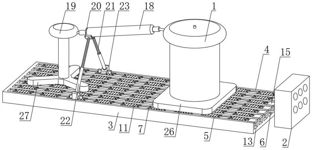
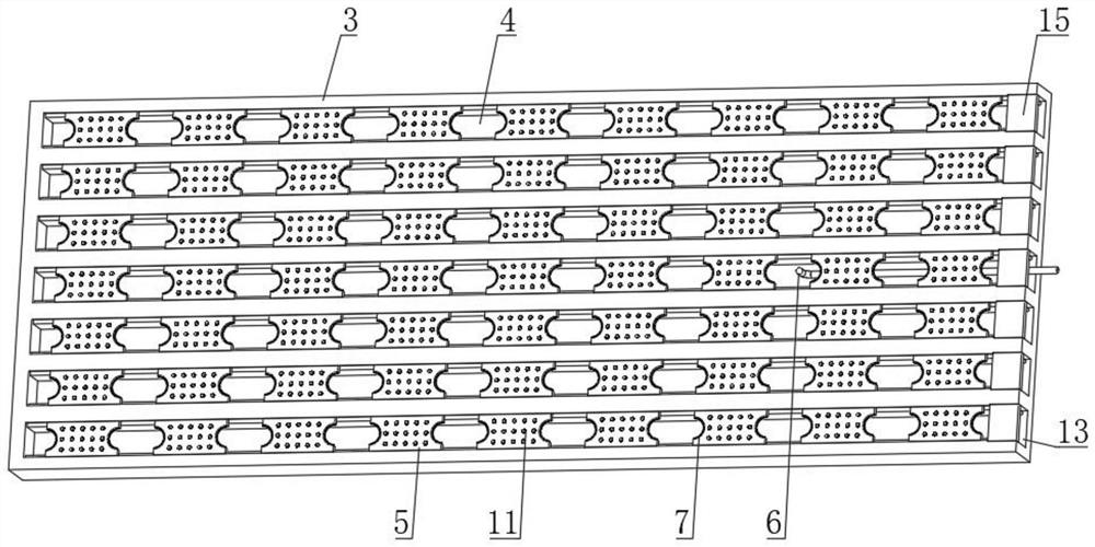
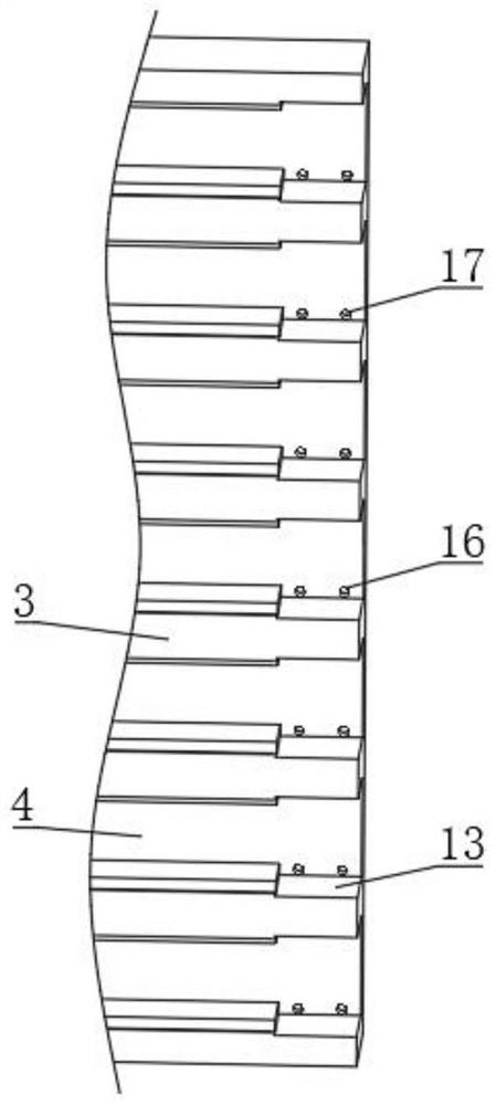
[0037] see Figure 1-8 , a protective device for a complete set of power frequency non-partial discharge test equipment, including a test transformer 1 and a control component 2 electrically connected to the test transformer 1, the control component 2 includes a partial discharge instrument, a control box, an isolation filter, and an isolation filter The power supply electrically connected to the device, this technical solution is the prior art, not shown in the figure, the output end of the test transformer 1 is electrically connected with a current limiting mechanism, the lower end of the test transformer 1 is provided with a base plate 3, and the upper end of the base plate 3 is horizontal A plurality of grooves 4 are opened, and a plurality of slide plates 5 are slidably installed on the upper end of the groove 4. The upper end of the slide plate 5 is provided with a heat dissipation mechanism. The inside of the groove 4 is provided with a test circuit 6, and both ends of t...


PUM


Abstract

The invention discloses a protection device for power frequency non-partial discharge test complete equipment, and belongs to the field of high voltage tests, the protection device comprises a test transformer and a control assembly electrically connected with the test transformer, the output end of the test transformer is electrically connected with a current limiting mechanism, and the lower end of the test transformer is provided with a bottom plate. A plurality of grooves are horizontally formed in the upper end of the bottom plate, a plurality of sliding plates are slidably installed at the upper ends of the grooves, heat dissipation mechanisms are arranged at the upper ends of the sliding plates, test circuits are arranged in the grooves, wire outlet grooves are formed in the two ends of the sliding plates, and one end of each test circuit extends out of the corresponding wire outlet groove and is electrically connected to a test transformer. And a protection mechanism is arranged in the wire outlet groove, so that the pulling force and the cutting force applied by electrical equipment and a user to a test circuit can be reduced, and the situations that the electrical equipment is damaged and leaks electricity due to fracture of the test circuit are reduced.

Description

technical field [0001] The invention relates to the field of high-voltage electric testing, and more specifically, relates to a protective device for a complete set of power frequency non-partial discharge testing equipment. Background technique [0002] For example, the authorized announcement number is CN111830299A, which discloses a cascade protection device for a new coupling test power frequency transformer, including a first small-level protection part and a second small-level protection part; the first small-level protection part is connected in series between the impulse voltage and the power Between the tested product and the voltage regulating resistor of the frequency overvoltage coupling test system; the second small protection part is the solid-phase arc extinguishing and shock-proof device; the solid-phase arc-extinguishing and shock-proof device is mainly used Composed of solid-phase arc extinguisher and graphite head for arc extinguishing, it protects the exp...

Claims


Application Information

Patent Timeline
Patent Type & Authority Applications(China)
IPC IPC(8): G01R31/12G01R1/02H02G3/04H05K7/20
CPCG01R31/12G01R1/02H02G3/045H05K7/20127
Inventor 张秀江王俊鲁部胡如存
Owner 江苏锦秀高压电器有限公司
Learn More